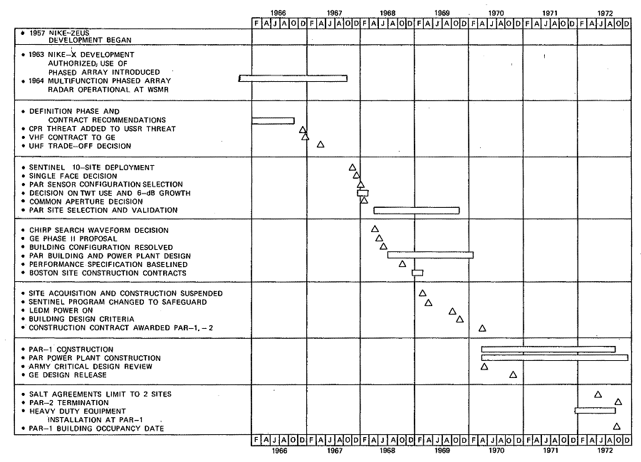
Figure 8-3. PAR Design History
Introduced in the Spring of 1965 as an adjunct to a full-scale NIKE-X deployment, the Perimeter Acquisition Radar (PAR) was to be an un-hardened, early warning VHF radar. Later in 1965, a limited NIKE-X deployment was proposed with the VHF PAR as one of its major components. This NIKE -X proposal triggered a 12-month "definition and contractor selection", phase for PAR. By October 1966, Bell Laboratories had established the PAR requirements and requested quotes from several major contractors. The proposals were received and evaluated by December 1966, and a contract was awarded for an "initial definition phase" [*] to General Electric Company (GE), Syracuse, New York.
[* - A two-phase effort was undertaken in which Phase I was Definition and Phase II Development.]
During this initial definition phase, detailed requirements1 were generated, a configuration was selected, and development of critical components was started.
A new deployment concept evolving from the NIKE-X program was introduced during January 1967 and designated 1-67. The 1-67 System deployment, later to become the SENTINEL System, consisted of SPRINT and SPARTAN missiles, Missile Site Radars (MSRs), and PARs.
In this concept, PAR was redefined from an early warning radar to one that could provide initial target detection, discrimination, and tracking for long-range SPARTAN intercepts. The additional requirements created by the new "area defense concept" redefined the PAR as a VHF radar in the forward portion of the defended area and hardened so that its integrity would be maintained during an attack.
In April 1967, after General Electric completed the Phase I VHF effort,1 the Phase II portion of PAR was temporarily delayed until a major problem could be solved. With the redirection of its role, PAR was now subject to nuclear blackout from the bursts of SPRINT and SPARTAN missiles. Results of a study on nuclear blackout, conducted the previous summer by the Institute for Defense Analysis, concluded that since the blackout problem was significantly less severe at UHF than at VHF, the PAR frequency band should be changed to UHF. Largely as a result of this study, a joint decision between Bell Laboratories, the Army, and the Department of Defense shifted the PAR operating frequencies to the UHF band. By May 1967, one month after the UHF decision, new detailed requirements for the PAR were established; many major configuration decisions regarding types of transmitters, number of faces, antenna size and type, and waveform types were determined; and the development of critical components was begun.
In September 1967, the decision was made to deploy the system embodied in the 1-67 (SENTINEL) proposal. Approval was given to General Electric to begin Phase II — the detailed design and manufacture of the PAR equipment.2-11 After defining the complete radar system configuration, the detailed design of the PAR building and power plant began in June 1968.
The planned PAR configuration12, 13 in many ways was similar to that of a Multifunction Array Radar (MAR-I — an L-band radar that has been constructed and thoroughly tested at White Sands Missile Range between 1964 and 1966). MAR-I had separate transmit and receive arrays and a one-to-one ratio of receivers and transmitters to antenna elements, but each array was corporate-fed, its transmitter used multiple Traveling Wave Tubes (TWTs), and its receiver used parametric amplifiers similar to those originally planned for PAR. Since the experience gained from MAR-I was directly applicable to PAR and components in the UHF band were thought to be available, much of the PAR design was considered to be "off the shelf." Development of a complete prototype system, therefore, was deemed unnecessary, [*] and it was decided to construct the first PAR [the Research and Development (R&D) model] at a site where it would become part of the operational system after the R&D phase was completed.
[* - As discussed in Part II — Management and Overall Approach —although this decision may have been satisfactory from a hardware standpoint, it led to severe system design penalties in the final ABM effort.]
In the SENTINEL Area Defense Plan, this site was to be located in the Boston, Massachusetts, area.
In March 1969, the SENTINEL Area Defense System was reoriented to the SAFEGUARD System Minuteman Defense Concept and the first two SAFEGUARD sites were selected in North Dakota and Montana, with North Dakota chosen as the R&D site for the PAR. (See Figure 8-1.) In lieu of an R&D radar for design confirmation, a Limited Engineering Development Model (LEDM) was constructed by General Electric. This provided a test bed for prototype models of components used singly in the system (e.g., the signal generator and exciter for the transmitter and the signal and data processor of the receiving chain) and for a significant quantity of each component used in large numbers within the final system (e.g;, antenna elements, phase shifters combiners, and transmitter TWTs).
Figure 8-1. PAR Site — North Dakota
Figure 8-2. PAR Transmitter
During 1969 and 1970, a major part of the PAR development and test activity involved use of the LEDM at Syracuse, New York. This program continued until May 1971 and verified the design and performance of the high-usage items. It established methods for their test and maintenance (including limited-life testing) and verified their interface with the rest of the system.
The PAR transmitter design (Figure 8-2) was approved in early 1970 and released for manufacture. Qualification testing of the TWTs by Raytheon was completed, the tube design was frozen, and production was started for the LEDM and the first PAR. Several hundred antenna elements and over 120 phase-shifter models were manufactured and tested in the LEDM. The low-noise transistor amplifier was developed, tested in the LEDM, and authorized for use in place of the parametric amplifier.
A construction contract was awarded for PAR-1 in North Dakota and PAR-2 in Montana in 1970 and actual construction12-13 began at these sites in April 1970. During the year, Critical Design Reviews (CDRs) were held by the Army resulting in the release of the PAR designs.
Toward the end of 1971, the Army Corps of Engineers installed the heavy duty equipment at the PAR-1 site. Work continued on both sites until August 1972 when, as a result of the Strategic Arms Limitation Treaty (SALT) Agreements, a decision was made to terminate any further work on PAR-2 in Montana. Figure 8-3 summarizes the PAR design history.
During the period from August 21, 1972 [Building Occupancy Date (BOD)] to September 27, 1974 [Equipment Readiness Date (ERD)], an intensive test program to verify system performance was executed.14 This is detailed in Figure 8-4. The majority of testing was implemented with software (see Chapter 4, SAFEGUARD System) developed at the Tactical Software Control Site (TSCS) at Madison, New Jersey. The success of the test and evaluation activity was largely due to the timely delivery of the many high-quality test software packages to the North Dakota PAR site. The software schedule is shown on Figure 8-5.
The initial alignment of the radar was completed by August 1973. During this month, the first satellite track and the first radio-star track were successfully accomplished.
Work continued past ERD to prove-in the PAR Weapons Process (PW) software for threat conditions exceeding those required at ERD. This included system testing of the PAR netted with the MSR and the Ballistic Missile Defense Center (BMDC). Additional work was scheduled beyond the Initial Operational Capability (IOC) date in April 1975 and would continue, during a Contractor Technical Maintenance program implemented by Western Electric Company, to final operational capability.

Figure
8-3. PAR Design History
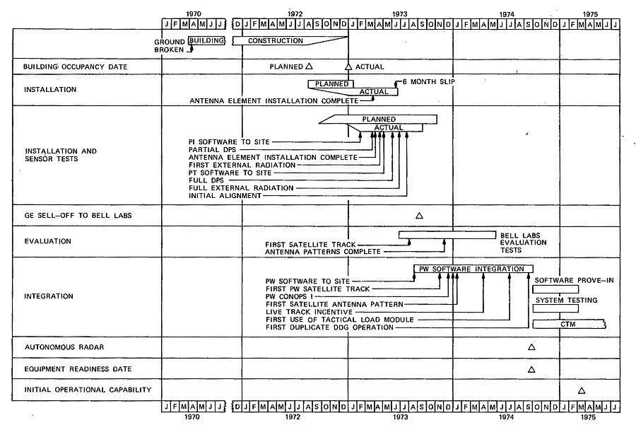
Figure
8-4. PAR-1 Installation and Test Schedule
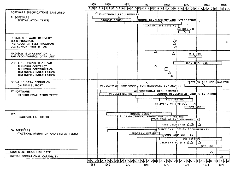
Figure
8-5. PAR Software History
The PAR is a phased-array radar, operating at UHF, which performs long-range surveillance to detect and track enemy ballistic missiles for intercept by the SAFEGUARD missiles. As an auxiliary function, it provides tracking data to North American Air Defense Command (NORAD) on selected satellites. The PAR is designed to perform its mission in an environment that may consist of false targets (aircraft, satellites, aurora, and meteors) and nuclear weapons effects. To withstand nuclear effects, the radar equipment is designed to meet specified environmental criteria.15 The radar is housed in a 128-foot high hardened reinforced concrete building that provides protection against nuclear thermal radiation and Electromagnetic Pulse (EMP) effects. The front of the building is inclined at a 25-degree angle from vertical, faces almost directly north, and supports a phased-array of 6888 antenna elements16 (Figure 8-6). The building required 17 million pounds of steel reinforcing bars and more than 58,000 cubic yards of concrete. The base of the structure is 200 feet square and 11 feet thick. The PAR face containing the radar elements is 7 feet thick. Adjacent to the PAR is an underground power plant connected by a 130-foot tunnel. A cutaway view of the radar is shown in Figure 8-7.
Figure 8-6 Face, Bottom-to-Top View of Phased-Array Antenna Elements
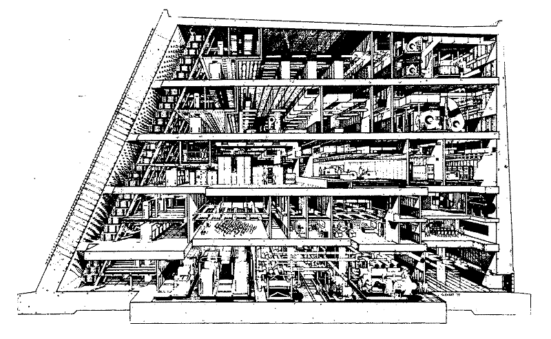
Figure
8-7. PAR Building, Cutaway View
The PAR searches the volume of space within a large solid angle in front of the array face at regular intervals. It can detect small targets in a typical ballistic missile complex at large distances with a high probability of detection. Both the radar operating frequency and the antenna beam-pointing direction can be varied rapidly. To optimize performance, separate antenna illumination functions are used in the transmit and receive modes. In the transmit mode, an asymmetrical phase taper is applied at low pointing angles to reduce the peak sidelobe power radiated toward the ground and enhance the system's electromagnetic compatibility.17 In the receive mode, an amplitude taper is used to reduce near-in sidelobes and minimize the effects of interference and jamming.
A block diagram of the radar is shown in Figure 8-8. The PAR transmitter consists of 16 groups of 8 (a total of 128) high-power TWTs, which amplify a chirped waveform generated by a common exciter. The combined total peak radiated power is in the multimegawatt range, and the transmitter operates at an unusually high duty cycle. The energy from each TWT is divided to feed two 24-element subarrays or a total of 48 elements.
Target returns are amplified by 256 low-noise transistor amplifiers, which are an integral part of the phase-steered, corporate-fed array. One transistor amplifier is used for each receive subarray of 24 antenna elements. The receive signals are combined into appropriately formed search and track beams and then are processed by an RF signal processor.
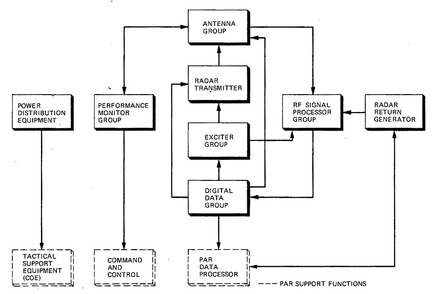
Figure
8-8. PAR, Block Diagram
The Digital Data Group (DDG) interfaces with the PAR Data Processor and provides timing signals and instructions for controlling the radar. Phase steering commands are generated in the DDG by the Beam Steering Computer (BSC). The digital equipment consists of two identical channels that operate simultaneously. Comparisons are made between the channels at numerous points to ensure errorless operation. This feature permits real-time fault detection and facilitates the isolation of a malfunctioning channel.
Radar performance is monitored by cyclic tests performed automatically every 50 milliseconds. Test signals are injected into a bidirectional element test network, which is used to distribute test signals to or from each antenna element for monitoring the receiver or for collecting samples of transmitter energy. Class A tests employ the element test network to monitor critical battle performance functions such as receiver sensitivity, transmitter power, and angle error. These tests are automatically interleaved with the tactical programs. Class B tests, performed on command by light-pen action at the Radar Maintenance Console, are used to monitor and display characteristics such as the transmit/receive antenna beam shape. Changes in the antenna beamforming alignment can be performed using Class B measurement data gathered through the element test network.
Equipment status is continuously displayed at the Radar Maintenance Console, where all performance and maintenance monitoring functions can be initiated by the console operator. Simulated test targets originated by the Data Processor are formed in the Radar Return Generator and injected into the signal processor's IF input.
The PAR subsystem performance requirements18 were met or exceeded in almost every instance. An extensive test program was carried out to assure design compliance with special environmental requirements.15 This program analytically assessed all the system components and performed experimental tests on a selected set of components representing each major design item. With the exception of the TWTs and certain retaining and fastening apparatus for which the vulnerability was assessed at 75 percent of the design level, all mission-critical equipment withstood the nuclear shock and vibration spectrum requirements.19
The PAR electrical performance parameters met or exceeded their required values in every instance. (See the Classified Supplement.) Due to higher transmitter power, better than expected receiver sensitivity, and slightly higher antenna gain, the overall system performance was about 4 dB greater than specified.17, 20
Power density measurements, made on the ground in front of the PAR while the radar was operating in the tactical search mode, showed that the average power density was well below the 10-milliwatts/square centimeter hazardous levels at all ranges. Other tests verified the PAR's electromagnetic compatibility with USAF aircraft and Canadian communication equipment.
Using an airplane-borne signal source, a somewhat limited antenna pattern measurement program (main beam and sidelobes) demonstrated that the internal method of injecting a signal at the element test coupler yielded results comparable to external measurements of an array-normal beam.21 The results showed agreement between the theoretical, internal, and external measurements within the stability [*] of the element path phase and amplitude values.
[* - This stability includes minor drifts on a short-term (days) basis.]
A view of the PAR with the antenna measuring radar on top of the building is shown in Figure 8-9.
Figure 8-9. PAR, Showing Antenna Measuring Radar on Top of Structure
Figure 8-10. PAR Traveling Wave Tubes
Figure 8-11. PAR Antenna Element
Figure 8-12. PAR Phase Shifter
VHF versus UHF
In 1967 when the PAR was changed from an early warning alert system to one that could provide tracking for the SPARTAN intercept role for area defense, studies were undertaken to redefine its capabilities in light of the new requirements.22-35 As mentioned previously, the Institute for Defense Analysis study of nuclear blackout effects as a function of frequency resulted in changing the transmitted frequency from VHF to UHF. In addition to the reduced severity of nuclear effects at UHF, this frequency band was expected to ameliorate disturbances caused by the intense aurora of the northern latitudes [**] and would be less likely to cause radio frequency interference problems.36
[** -Bell Laboratories conducted a study at Prince Albert Radar Laboratory in Canada to investigate auroral effects at UHF.36]
However, since there would be less target enhancement due to length resonance effects and some loss in equivalent target cross section at the higher frequency, an increase in the power aperture product was required. The UHF implementation required an increase in transmitter power by a factor of four. This increased cost was offset by the use of novel, block-combining techniques in the receiver and adaptation to a single, common transmit/receive array in place of the previous dual aperture design. The common aperture required less space, fewer elements, and only a single set of beam steering hardware and element phase shifters. Although a space feed was planned for the MSR, the extremely large anechoic chamber required by the PAR at UHF was considered impractical and wasteful of space in a hardened structure. Hence, a corporate feed, similar to that of the previous MAR, was used for the PAR.
Transmitter
After considerable study22-35 and review, TWTs (Figure 8-10) were finally chosen for the transmitter power amplifier. Several factors were involved in this selection.
• The tube was expected to have high reliability and long life (30,000 hours) since it was a scaled model of the proven L-band design developed jointly by Bell Laboratories and Raytheon for use in the NIKE-X MAR.
• The power output per tube made it a convenient unit to provide the required total summed power of 128 tubes.
• The choice enhanced reliability because of the inherent redundancy of multiple transmitter power sources.
Previously, tetrodes had been a leading contender in the General Electric design, but their reliability could not approach that of the TWT and power output would have had to be sacrificed for bandwidth. Solid state power amplifiers were also investigated, but their cost was not competitive with the TWT and there was little background to assure the development of such a transmitter within the time schedule.
The choice of a transmitted pulse waveform was related to the transmitter decision and involved some interesting tradeoffs. In working with solid state transmitters, consideration must be given to using a long, 6-millisecond, CW pulse to minimize peak power. When the decision was made to use the TWT, the required pulse energy could be obtained with higher peak power and shorter pulses. The desired range resolution was obtained using a chirped pulse with a compression ratio of 100 to 1.
The decision to use a chirped pulse provided a second-order benefit as demonstrated by the Prince Albert Radar studies .3S It was found that in an auroral environment, the clutter returned was approximately proportional to the size of the range resolution cell. Therefore, a chirped pulse would return less clutter than an equal energy CW pulse, roughly in proportion to the chirp compression ratio. In addition, with a chirped system, the signal processor was much reduced in complexity since a single dechirp filter replaced the banks of filters, each matching a different doppler frequency, which would be required for a pulsed CW, search signal processor. Dispersive delay lines needed for the chirped pulse were available from the ZEUS Acquisition Radar and were modified for use in the PAR.
Antenna Element
The high powered, hardened elements (Figure 8-11) were one of the most vulnerable entities in the PAR design. General Electric was required to design them to withstand the combined direct effects of the blast and elevated temperatures of a nuclear explosion. The final design consisted of crossed-dipoles fabricated from beryllium copper, and inclined 45 degrees toward the array face. Phase correcting stubs were placed midway between each element to decrease the polarization ellipticity at wide scan angles. A Hardness Verification Test Program37 (see Chapter 6) proved the capability of these elements to withstand nuclear attack with minimal degradation of electrical and mechanical properties. Environmental tests verified their ability to perform despite severe rain, ice, or snow accumulation.
Phase Shifter
Another notable development was the phase shifters (Figure 8-12), which are located directly behind the array and provide both transmit and receive beam steering.
Several designs were considered, including ferrite phase shifters, a lumped-constant micro-strip phase shifter similar to the MSR unit, and a distributed constant diode-switched transmission line configuration. While the lumped-constant microstrip device was smaller and tended to simplify space and maintenance requirements, its advantages were not considered significant when the PAR deployment was reduced to one site. The final design used high power PIN diodes for switching in an air-dielectric strip transmission line.
Extensive low-power and high-power tests were performed on these diodes to evaluate their characteristics and confirm their reliability.
Receiver RF Amplifier
Parametric amplifiers were initially considered for the PAR RF receive amplifiers because of their low-noise figure and the experience gained from their use in previous MAR designs. The improvement in low-noise transistors over the years, particularly some developed by Texas Instruments [*] for this frequency band, indicated that a transistor RF amplifier had definite advantages.
[* - Before transistors of reasonable yield, high performance, and reliability were finally delivered by Texas Instruments, a great deal of consultation, assistance, and technical direction was required from several Bell Laboratories technical areas.]
The transistor amplifier was smaller, less expensive, easier to adjust and maintain, and had an improved noise figure and significantly lower power requirements than the parametric amplifier.
Maintenance and Redundancy
The maintenance philosophy was based on a balance of component availability/reliability38 versus the cost of providing redundant units. The result of this balance was to provide redundant exciters, waveform generators, angle error detectors, analog-to-digital converters, radar control and conditioner units, beam steering calculators, and input-output controllers. The redundant Digital Data Group was designed to operate synchronously with the on-line unit. Error detection was designed to compare signals and, under software control, to automatically switch to the "good" unit. Redundancy was also built into the Data Processing System by providing one spare unit in each of the Processor, Program Store, and Variable Store Units of the Central Logic and Control.