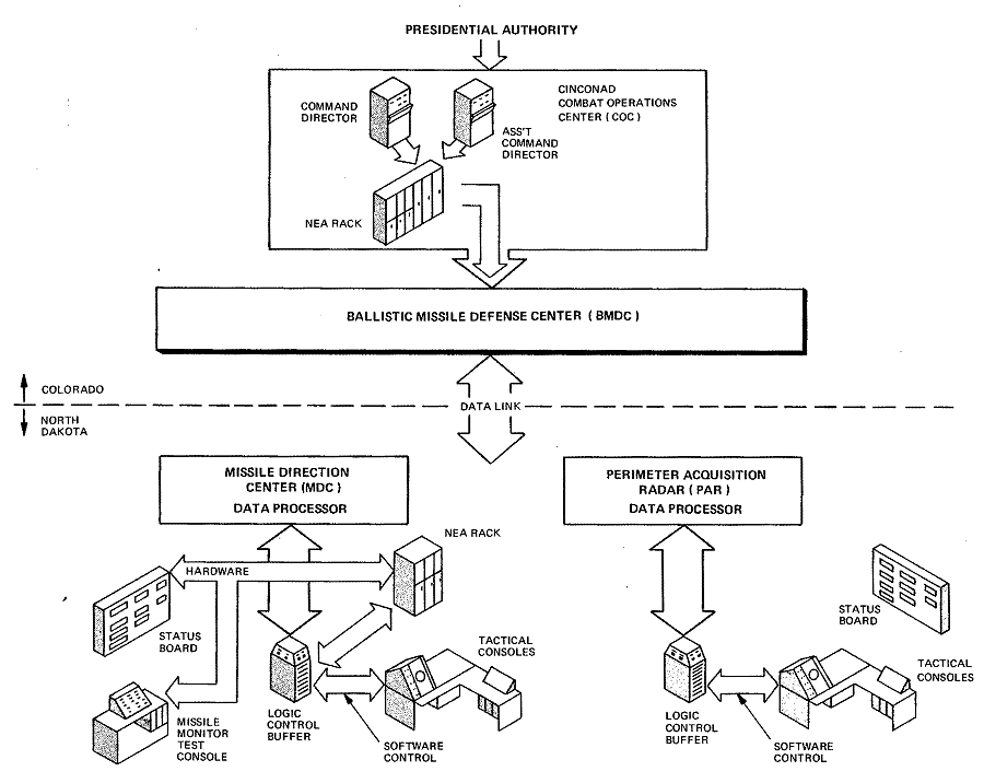
Figure 12-1. Overview of Command Hierarchy
The Ballistic Missile Defense Center (BMDC) is the highest echelon of command and control in the SAFEGUARD System. The Commander-in-Chief of the Continental Air Defense Command (CINCONAD) exercises operational command through the BMDC. The BMDC, in turn, directs the activities of the Perimeter Acquisition Radar and the Missile Direction Center, and controls the launch and burst of nuclear missiles. BMDC facilities are collocated with the CINCONAD Combat Operations Center (COC) in the Cheyenne Mountain Complex of the North American Air Defense Command (NORAD).
The BMDC provides a single-point interface for the Commanding General of the U.S. Army SAFEGUARD Command, whose forces staff the SAFEGUARD System, and CINCONAD, who is charged with the defense of the continental United States against air attack. After receipt of presidential authority to release nuclear weapons, the CINCONAD COC authorizes using the SAFEGUARD System's stockpile of nuclear missiles by entry of the Nuclear Employment Authority (NEA) at the COC. The BMDC, by consolidation and retransmission, provides the COC with the information necessary to support the authorization. (See Figure 12-1 for an overview of the SAFE GUARD, command hierarchy.)
The BMDC also supports the SAFEGUARD System's mission by processing and consolidating early warning data on detections made by non-SAFEGUARD sensors, e.g., data the SAFEGUARD System needs to respond to submarine-launched ballistic missiles.
The COC/BMDC interface provides the SAFEGUARD System with alert and readiness-level coordination with other defense systems as well as coordination with the Strategic Offensive Missile Forces of the Strategic Air Command. The BMDC sends SAFEGUARD-generated early-warning, attack-assessment, and satellite-observation data to the COC.
SAFEGUARD System Command authorized development of the BMDC Subsystem in April 1970.
Analyzing the hardware support required for the subsystem's development revealed that the Tactical Software Control Site at Madison, New Jersey, might not be suitable. Arrangements therefore were made for early delivery of the tactical hardware to Guilford Center, North Carolina. This hardware, eventually destined for Cheyenne Mountain, was in Guilford Center ready for use by the software developers in September 1972. It was named the Early Ballistic Missile Defense Center (EBMDC).

Figure
12-1. Overview of Command Hierarchy
The system development consisted essentially of three versions of the Weapons Process: BW1.0, BW 1.1, and BW1.2.
The initial version, BW1.0, was released in December 1972, and contained the necessary interfaces and responses to satisfy the four-site deployment.
The second version, BW1.1, was released in June 1973. It was developed from information for a single-site deployment and contained corrections which were revealed by the test program for BW1.0. The EBMDC was removed from Guilford Center in August 1973, and in January 1974 was ready for use in Cheyenne Mountain.
In February 1974, BW1.2 was installed. This version included all features known to satisfy the requirements of single-site deployment. However, as a result of the functional and system test program, new Tactical Load Modules were periodically created until, on August 15, 1974, a final version of BW1.2 was released. This version was tested and turned over to the Army on October 1, 1974, thereby completing development of the BMDC.
The BMDC contains a minimal, nonredundant processor using standard SAFEGUARD hardware. This processor primarily performs command, control, and display functions.
Hardware
The hardware consists of a Central Logic and Control, a Recording Subsystem, a Command and Control Display Subsystem, a Data Transmission Controller Subsystem, and a Maintenance and Diagnostic Subsystem.
Central Logic and Control (CLC)
The CLC used is the minimum configuration capable of supporting the BMDC mission. A non-redundant CLC is justified at the BMDC since it does not control radars or in-flight defensive missiles. The site mission can allow a significantly reduced Availability/Reliability Product without materially affecting the overall SAFEGUARD defense capability. In view of this reduced requirement, the standard SAFEGUARD hardware was considered sufficiently reliable.
The CLC for the BMDC consists of one Digital Data Processor Unit, three Program Store Units, three Variable Store Units, one Input/ Output Controller, and one Timing and Status Unit. This is a "1-3-3-1-1" configuration.
Recording Subsystem (RSS)
The RSS used in the BMDC includes only those components required to support BMDC operations. These components are four disk memory units, four magnetic tape transports, two computer output printers, and one punched-card reader.
Command and Control Display Subsystem (CCDS)
The CCDS associated with the BMDC includes man/machine interface facilities to allow rational, manual control of the BMDC and the system as a whole. The major elements of the CCDS are briefly described in the following paragraphs.
BMDC Commander's CRT Console. The BMDC Commander's CRT Console enables the Commander to exercise manual control actions — such as Hostile Identification Enable, SPARTAN Hold Fire, and Nuclear Enable Inhibit — over the SAFEGUARD System.
In addition, the BMDC Commander may invoke Hold Fire, Cease Engage, and Force Intercept on individual targets. The associated CRT display provides the information needed to perform these manual actions.
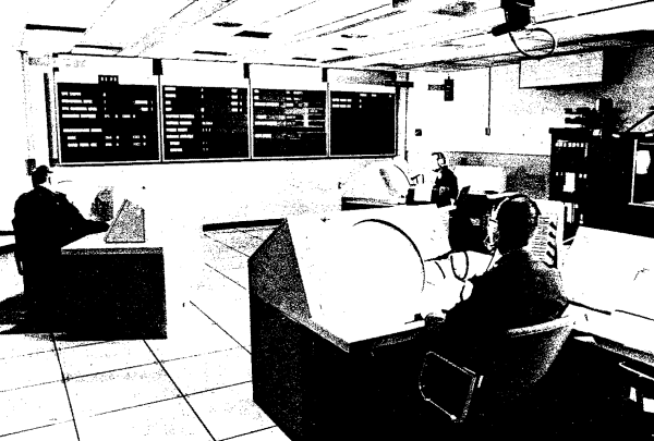
Command and Control Consoles. The CCDS also includes three general-purpose Command and Control Consoles. These consoles provide operating positions for the BMDC Tactical Director, Assistant Tactical Director, and System Capability Officer. At each console, any of the roles can be assumed without degrading manual capability. The console position normally manned by the Tactical Director does not include a teletypewriter, while those positions normally manned by the Assistant Tactical Director and the System Capability Officer do have teletypewriters. Figure 12-2 shows the three Command and Control Consoles as installed in the BMDC Operations Room.
Through his console position, the Tactical Director may exercise control over the entire SAFEGUARD System as well as control over the launch and burst of individual missiles. This degree of control is provided by manual actions, such as System Defense Mode Control, Missile Allocation Control, Hostile Identification, Hold Fire, and Cease Engage. The associated CRT display provides the information needed to perform these manual actions.
The Assistant Tactical Director's console allows this officer to support the Tactical Director. The teletypewriter at the Assistant Tactical Director's position allows manual entry of certain tactical messages normally received from the CINCONAD COC via the data link, thereby providing an alternate route for these messages.
The System Capability Officer's console informs that officer about BMDC hardware and software. In addition, the position permits the officer to restructure the BMDC Weapons Process to make optimum use of available resources as the tactical environment changes.

Figure
12-2. BMDC Operations Room with the System Capability Officer (left),
Tactical Director (foreground), Assistant Tactical Director (right
rear), and System Status Display Unit (rear)
The System Capability Officer receives enough data about the SAFEGUARD System as a whole to allow him to advise the BMDC Commander and Tactical Director about the system's capability. From this data, he also may coordinate maintenance for the entire system. The teletypewriter at this console position enables the System Capability Officer to inform the COC about the BMDC.
System Exercise Console. The System Exercise Console is used by the BMDC Exercise Director to manually control and monitor a single-site or multisite exercise.
In addition to the CRT console, the BMDC Exercise Director's position includes a teletypewriter so that he can manually modify the simulated system posture as well as the posture included in the system exercise.
Data Management Console. The Data Management Console allows manual monitoring of the data links connecting the BMDC with appropriate components of the overall system.
This non-CRT console permits intersite time synchronization of the BMDC Weapons Process with the interfacing SAFEGUARD System sites. In addition, the Data Management Console permits testing of the Data Transmission Controller, the Data Transmission Controller Adapter, and the connecting data links. This console position also includes a teletypewriter, which can be used to enter parameters and receive status reports from the Data Processing System (DPS) concerning the intersite data links.
Data Processing Console. The Data Processing Console permits the Data Processing Officer to manually control the subsystem's hardware and software.
In addition to the facilities provided by the CRT console, the Data Processing Officer's normal position includes two teletypewriters. These machines allow the officer to enter parameters and receive status reports about the subsystem's hardware and software. One of the teletypewriters is in an active mode and the other is in a standby mode.
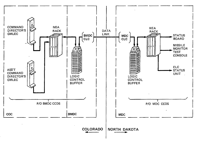
Guided Missile Launch Enable Group. (See Figure 12-3.) The Guided Missile Launch Enable Group (also known as the NEA rack) is peripheral to the BMDC through the Command and Control Display Subsystem. The Guided Missile Launch Enable Group is in the CINCONAD COC. Two Guided Missile Launch Enable Controllers (GMLECs), also located in the COC, are used to release the NEA message. By virtue of the interface parameters, the Guided Missile Launch Enable Group appears to the Command and Control Display Subsystem as a special-purpose teletypewriter.
The signals generated when the Guided Missile Launch Enable Group is manually activated are related to the authorization by the National Command Authority to employ nuclear weapons. These signals require special handling by the BMDC Weapons Process. The NEA data is identified by the unique entry point in the hardware.
System Status Display Units. The System Status Display Units (Wall Status Panels) and Site Readiness Level Signs, with the associated System Status Display Support Unit, display data about the site and system status, National Defense Posture, and readiness and alert levels. The System Status Display Unit in the BMDC Operations Room (Figure 12-2) is a secondary display because most of its information is available on other display media, such as the CRT consoles.
The Site Readiness Level Signs and System Status Display Units in the Maintenance Control Center are more important. They are the primary source of information concerning alert and readiness status for personnel manning the center. The System Status Display Unit in the Operations Room is monitored by the COC through closed-circuit television as a major source of data about the SAFEGUARD System. This is an interim arrangement pending completion of the data link between the COC and the BMDC.

Figure
12-3. Nuclear Employment Authority Interface
Data Transmission Controller Subsystem
The Data Transmission Controller associated with the BMDC includes the appropriate logic modules to support an interface with three data channels. The data rate in the BMDC Data Transmission Controller is set at 4800 bits per second.
The SAFEGUARD System requires a data-link connection to the NORAD Communications Processor, which in turn provides a data interface with the CINCONAD COC and the Space Computational Center, both collocated with the BMDC in the Cheyenne Mountain Complex.
A data link from Cheyenne Mountain (Colorado) to Grand Forks Air Force Base (North Dakota) connects the BMDC to the remainder of the SAFEGUARD System (see Figure 12-1).
Maintenance and Diagnostic Subsystem (M&DSS)
The M&DSS at the BMDC includes maintenance-related equipment for computation, auxiliary input/output operations, and auxiliary information retrieval. It also provides the man/ machine hardware interface to implement or support certain CLC loading and initialization operations, certain DPS recovery operations, and certain hardware fault isolation procedures.
Software
The BMDC software consists of a basic tactical software package (the BW1 Process), the Tactical Operating System, a Basic Operating System, the CLC Control Facility, and appropriate M&D software.
The following paragraphs describe these software components, setting forth their unique characteristics and their interrelationships.
BMDC Weapons Process
The BMDC Weapons Process (BW1) meets the standards imposed by the DPS performance requirements.
[See reference number 40 in References for Chapter 4.]
The BW1 is designed to create a software process that can adequately control error conditions and to provide a structure that can be efficiently maintained. Since the BW1 employs a single processor, the design must permit the system exercise function to co-exist with the weapons process in the DPS, yet it must be invisible to the tactical portion of the process.
To attain these goals, the BW1 was partitioned into five functional areas. These are the Process Coordination Major Functional Area, the BW-Operations Major Functional Area, the Displays and Controls Major Functional Area, the Intersite Communications Major Functional Area, and the System Exercise Major Functional Area. The following paragraphs present an overview of each Major Functional Area.
Process Coordination. This area is responsible for management and surveillance of the BW1 during tactical or system exercise, real-time operation, initialization, and termination.
BW1 programming tests for errors in the data base and in execution. The normalized cumulative error levels can be displayed to the BMDC System Capability Officer as an indication of subsystem sanity. Also, the Process Coordination Task and the Working Interface Table Request Processor Tasks provide the request and responses necessary to establish and terminate a system exercise.
BW-Operations. This area is divided into eight tasks: the Operational Mode Determination Task, the Visible Threat Consolidation Task, the Defense Status Consolidation Task, the Alert and Readiness Level Dissemination Task, the Nuclear Weapons Control Task, the Special Acquisition and Track Assignment Task, the Defense Mode Determination Task, and the NEA Transmission Task. The first seven of these tasks are cyclically enabled. When they execute, they determine if there are messages or manual actions to be processed.
The NEA Transmission Task is unique in its method of enablement. This task is enabled whenever the coded NEA messages are presented to the specially designated teletypewriter port of the Logic Control Buffer in the CCDS hardware (see Figure 12-3).
Displays and Controls. This area provides the software to drive consoles, displays, and teletypewriters of the Command and Control Display Subsystem. Because of the magnetic-core-size limitations for the BMDC Weapons Process, the Displays and Controls Major Functional Area uses disk-to-Variable-Store overlay extensively.
Intersite Communications. This area detects and validates messages from netted sites; it also formats messages to netted sites. In addition, this functional area monitors and evaluates communication links and maintains intersite time information. Manual access to the Intersite Communications Major Functional Area is provided by the Data Management Console. Upon successful completion of a DPS recovery, this area initiates the intersite messages necessary to update the BW1 data base.
System Exercise. This area supports both local and multisite system exercises for the BMDC, while remaining invisible to the tactical portion of the BMDC Weapons Process. In addition to certain control operations, such as initiation, termination, error recovery, and displays, the System Exercise Major Functional Area can simulate the tactical data interfaces with the Missile Direction Center and/or the NORAD Communications Processor (Combat Operations Center/Space Computational Center). Simulation of the Missile Direction Center implies simulation of the Perimeter Acquisition Radar. In any exercise mode, this functional area simulates all sites which interface with the BMDC but which are not participating in the exercise.
Tactical Operating System (TOS)
The TOS controls the real-time execution of SAFEGUARD DPS programs. This control involves sequencing programs, transferring data between storage and the peripheral devices, detecting errors and recovering from them, assigning available hardware as required, periodically testing DPS equipment, managing the CCDS and RSS, and providing communications and logic for controlling the operating system.
Basic Operating System (BOS)
The BOS provides a debugging environment for tactical software integration on the CLC. It allows single-processor, non-real-time execution on the CLC and facilitates manual interaction for patching, dumping, testing, and disc maintenance. Although the tactical software will function without BOS, the system provides essential tools.
CLC Control Facility
The CLC Control Facility provides the basic configuration, control, and loading functions required to do the following: to initially load the CLC and to reconfigure and recover the DPS, to partially or completely load the CLC, and to reinitialize the data base. Additionally, the CLC Control Facility provides such utility functions as a mathematics package, number conversion routines, time-of-day formatting, device allocation, device status management, a software interface with the CLC Status Unit, and string manipulation.
Maintenance and Diagnostic Software
The M&D software consists of a combined executive/utility system, which is resident in the M&D Processor; development programs that are used to build and debug all M&D Processor software; and user-oriented programs for hardware maintenance.
The BMDC subsystem delivered to the government on October 1, 1974, fully meets all performance objectives as delineated in the various design control documents.
Performance Measurement
Four tests measured the capability of the subsystem to meet the performance objectives: the Unit Test Sequence, the Progression Test Sequence, the System (End-Point) Test Sequence, and the Netted System Test Sequence.
Unit Test Sequence
The Unit Test Sequence verified that the performance of each distinct software module of the Weapons Process could meet the requirements imposed by the Functional Design Specification.
Progression Test Sequence
The Progression Test Sequence verified that each newly released Tactical Load Module could meet the performance requirements imposed by the design control documentation. The Progression Test Sequence measured the performance of the subsystem for given tasks, e.g., Visible Threat Consolidation, Defense Status Consolidation, etc.
System Test Sequence
The System Test Sequence verified the functional capability of the complete subsystem Tactical Load Module operating under a stress or load condition. Subsystem response was derived from intersite messages and visual indications available through the display media in the subsystem.
Netted System Test Sequence
The Netted System Test Sequence is part of the System Integration and Evaluation Test Plan, which supports the overall SAFEGUARD System performance evaluation. The Netted System Test Sequence is a series of tests which evaluate the performance of the system in normal peacetime as well as in simulated attack conditions.
Performance Measurement Analysis
The data yielded by the four test sequences helped to validate the subsystem performance. The raw collected data was processed off-line using the SAFEGUARD Data Reduction System. The performance of the subsystem as evidenced by the reduced data was then compared to the performance objectives. Correlation between the reduced data and the predicted performance was considered to be evidence of attaining the performance objective in question.
By using this criterion, the subsystem was judged to meet all performance objectives imposed by the design control documentation.