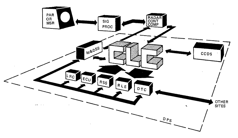
Figure 11-1. Data Processing System
SAFEGUARD radars and missiles are directed and controlled by programs executed on the Data Processing System (DPS).1 The primary function of the DPS is to perform all calculations necessary to identify and track the threat, to allocate and determine the point at which the threat can be intercepted, and to generate orders necessary to launch and guide defensive missiles to the intercept point. The Command and Control Display Subsystem (CCDS) of the DPS provides the interface between man and the system for nuclear weapons release, monitoring of automatic operation, and manual control, if required. Other major DPS interfaces include the Perimeter Acquisition Radar (PAR) or Missile Site Radar (MSR), the missile launch area (MSR only), and the data communications links to other SAFEGUARD sites. A Maintenance and Diagnostic Subsystem (M&DSS) locates and corrects trouble; a Recording Subsystem (RSS) monitors the system; and a System Readiness Verification (SRV) Subsystem exercises and evaluates the system.
The DPS was developed in two steps, DPS-1 and DPS-2. In 1963, Bell Laboratories, with UNIVAC as a major subcontractor, began developing DPS-1 for NIKE-X. A prototype system was operating at Whippany in 1967. A second system was later installed on Meck Island. At that time, development of DPS-2 was started to meet the requirements of the SENTINEL deployment, with the initial prototype checkout at Whippany targeted to begin in 1970. Bell Laboratories was the primary design agency, with Lockheed Electronics as a major subcontractor for memories and UNTVAC for design of the processor. DPS-2 was not a new design but rather a major modification2 of DPS-1 to improve the ease and economy of manufacture and test, and to achieve higher operational reliability, increased throughput, and ease of maintenance. To achieve these ends, design improvements were concentrated in the following areas:
• Addition of the M&DSS, providing a programmable maintenance, diagnostic, and operation interface with the digital hardware via an automatic data bus
• Provision of a flexible DPS partitioned-system capability with complete hardware independence
• Simplification of input-output and peripheral device programming via hardware modifications
• Standardization of DPS-2 interfaces
• Use of 500-nanosecond core memory for both program and variable store (DPS-1 used 200-nanosecond coupled-film memory in addition to 500-nanosecond memory)
• Improvements in basic digital hardware, such as connectors, cold plates, etc.
• Use of beam-leaded Integrated Circuit Packages (ICPs)
• Use of a multiple disc-drive (disc pack) file bulk-memory system
• Development of tactical Cathode-Ray-Tube (CRT) consoles.
The first configuration of DPS-2 was installed and successfully checked out at Whippany beginning in 1970. Installation and checkout of a second system began at the Tactical Software Control Site (TSCS) in Madison the following year.
Figure 11-1 shows the relationship of the DPS to other elements of a SAFEGUARD site. The heart of the system is the Central Logic and Control (CLC), a multiprocessor, high-speed digital computer complex that interfaces directly with the radar and the CCDS. In addition to the CCDS, peripheral devices include the Exercise Control Unit (ECU), which is a part of the System Readiness Verification (SRV) Subsystem; the Data Transmission Controller (DTC); the M&DSS; the RSS; the Remote Launch Equipment (RLE); and the Logic-to-Relay Converter (LRC). The RLE and LRC are used only with the MSR. A brief description of each major component follows.
Central Logic and Control (CLC)
The CLC executes the programs that direct the operation of a SAFEGUARD site. It is a modular, multiprocessor system that performs all data processing and logical operations in the DPS in real time.3 Multiprocessing permits as many as ten Digital Data Processors to simultaneously execute separate tasks or distinct parts of the same task. Multiprocessing also allows a number of unrelated programs to be processed at one time, thereby reducing any work backlog.
Its modular design enables the CLC to meet the requirements of a particular site, and permits it to be partitioned [*] into two separate and independent computer systems4 when required either for system exercises or for maintenance operations. These two systems are designated "green" and "amber. "
[* - Partitioning of the CLC into two distinct systems is discussed under System Readiness Verification.]

Figure
11-1. Data Processing System
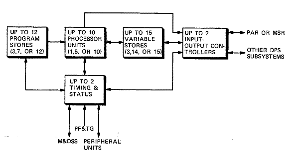
Figure 11-2 shows a block diagram of the CLC, which consists of:
• Digital Computer Group
a. Digital Data Processor Units (PUs)
b. Program Stores (PSs)
c. Variable Stores (VSs)
d. Input-Output Controllers (IOCs)
e. Timing and Status (T&S)
• Precision Frequency and Time Generator (PF&TG)
• CLC Monitor (CM) (only used in TSCS).
Three basic equipment configurations meet the specific data processing needs of the three SAFEGUARD sites. Supporting the MSR is a 10-12-15-2-2 system consisting of 10 PUs, 12 PSs, 15 VSs, 2 IOCs, and 2 T&S racks. The PAR requires a 5-7-14-2-2 configuration, and a 1-3-3-1-1 configuration is used in the Ballistic Missile Defense Center (BMDC). There also is one PF&TG with each configuration. The CLC Monitor is used only in TSCS and is not a part of a tactical site. Interconnection between racks is through interface switching units built into each rack. To achieve nearly continuous operation as economically as possible, the CLC employs "n+1" redundancy.5 Each of the five types of elements has a single replacement that is not required for running the application software and is therefore redundant. For example, if the application software requires 12 racks of program store for execution, then at least 13 are provided. The "n+1" element can be switched in to replace a failed element.
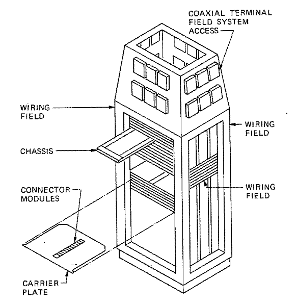
The SAFEGUARD hardware concept permits fabrication of the DPS from a standard stock of racks, chassis, and integrated circuit packages. The design is based on integrated circuit technology using a modified direct-coupled transistor logic circuit having circuit delays in the 5- to 6-nanosecond range.6 The hardware provides a flexible system for interconnecting groups of integrated circuit packages on chassis, and chassis into racks as shown in Figure 11-3. Wire-wrapping the integrated circuit package connections on the chassis enhances their reliability. Each chassis accommodates 275 integrated circuit packages, which represent more than 600 logic circuits. As shown in Figure 11-4, the chassis are housed in the water-cooled rack with two chassis mounted side by side on a chassis carrier plate that locates, supports, and cools the chassis. The chassis carrier plates are mounted at a 1-inch vertical pitch within the rack. There is a maximum of 59 levels in the rack housing 118 chassis.
Figure
11-2. Central Logic and Control
Figure 11-3. SAFEGUARD Digital Racks
Figure
11-4. Construction Details of SA FEGUA RD Digital Rack
The CLC required more access connections to the chassis than could be provided with rear access only. Therefore, both sides of the chassis are used for additional access terminals. The rear contacts to the chassis are made in a conventional plug-in manner. On the side, a linear-actuated cam arrangement engages the contacts after the chassis is properly positioned in the rack. Thus, wiring fields exist on three sides of the rack. In addition, internal connections are provided at the interface between chassis. The chassis are side by side on the carrier plate to provide near-neighbor connections between groups of chassis. In total, the rack has more than 40,000 possible signal connections. Since each rack has wiring on three sides, the racks must be arranged in a diamond pattern to allow physical access to all four sides of a rack.
Rack-to-rack interconnections are provided by plug-in coaxial terminal fields at the top of the rack, which allows as many as 11,520 connections.
To preserve the integrity of high-speed pulse transmission between the various units of the multiprocessor, a characteristic impedance of 100 ohms is maintained for the transmission of all signals. Coaxial cables are used for all connections between racks and for all rack-wiring runs longer than 5 feet. Twisted pair wiring predominates in the rack. The chassis connector maintains a fixed impedance across the connection by providing both a signal and a ground path using a highly reliable double-contact arrangement to enter a chassis.
The memory racks include a 16K by 68-bit-per-word core memory unit and the associated interface logic switching circuits, which provide interconnection to the multiple units. The core memory units are air-cooled. They operate at a cycle time of 500 nanoseconds and have an access time of 300 nanoseconds.
Digital Computer Group
Digital Data Processor Unit (PU).7-9 The PU performs all arithmetic and logical operations for the CLC. As a part of a multiprocessor system, each processor operates asynchronously with respect to the memories, Input-Output Controller (IOC), and other processors. The processor is divided into five sections: Program Control Unit (PCU),10 Arithmetic Control Unit (ACU), Operand Control Unit (OCU),11 Program Interface Switching Unit (Program-ISU), and Operand Interface Switching Unit (Operand-ISU). The five sections operate in parallel, with minimum control between sections. The main function of the PCU is to fetch instructions from Program Store and distribute them to the ACU and OCU. The ACU performs the arithmetic and logic operations. The main function of the OCU is to fetch and store operands for the ACU. The ISUs provide the communication links for the processor, the memories, and IOC.
Program Store (PS).12,13 The PS accommodates the executive program and the assigned programs used in the CLC. These programs are instruction words temporarily held in PS for subsequent transfer (fetching) to a requesting unit. The Store Transfer Unit (STU) in the T&S rack can store or fetch programs on request; however, the PU can only fetch programs. Therefore, loading and revising the contents of the PS must be performed via the STU. Each PS is divided into two independent, identical halves (A and B) each comprising an 8K memory and an ISU.14, 15 A processor can have interleaved access to the two halves within a PS. This reduces the effect of queuing. Interleaving involves arranging the address structure of a program so that adjacent words reside in the independent halves of the memory. The 8K memory is a ferrite-core, magnetic memory system having a storage capacity of 8192 68-bit words.
Variable Store (VS).13,16 The VS stores operand data that is modified from time to time by the PU and provides temporary storage for programs. The IOC and the PU OCU can store or fetch data and can also store programs; however, only the PU PCU can fetch these programs. Transfer requests can be for the left half of the word (byte 1), for the right half (byte 2), or for the entire 68 bits (both bytes). Each VS is composed of a 16K ferrite-core, magnetic memory and an ISU.15,17 Memory word length is 68 bits.
Input-Output Data Controller (IOC).18-22 The IOC is a special-purpose computer that relieves the PUs of the time-consuming input-output operations. The PUs operate much faster than their peripheral devices and therefore would be slowed down or tied up if required to execute I/O instructions. Since the CLC is a multiprocessor system, the PUs would be competing with each other for access to peripheral devices, creating queuing problems if IOCs were not used; therefore, the IOC controls the flow of information between variable storage and the peripheral devices. Each peripheral device is connected to the IOC via one of 16 available channels.
Timing and Status (T&S) Rack.23-24 The T&S rack has three essentially autonomous units that perform four main functions in the CLC. The Timing Generator (TG)25 provides real-time synchronization. The STU provides the means for writing data into PS. The Status Unit (SU) provides a means to assemble and evaluate system status information and to partition the DPS. The control of these units is provided through the Interface Transfer Unit (ITU), Interface Switching Units (ISUs),15, 26 and the Channel Control Unit (CCU).
Precision Frequency and Time Generator (PF&TG)27
The PF&TG provides precision frequencies and a time-of-day output for the DPS. It contains an oscillator that generates a 5-megahertz base frequency. This base frequency is multiplied and divided to produce the wide range of precision frequencies required by various units in the DPS. Time-of-day outputs are generated and distributed to synchronize events with real time. An external frequency standard is used to calibrate the 5-megahertz oscillator. The equipment is housed in an air-cooled rack. In case of power failure, a battery rack supplies emergency power to the 5-megahertz oscillator.
Central Logic and Control Monitor (CM)28
This unit is not a part of the tactical system but was designed and built for TSCS to aid the initial hardware-software checkout. It checks and records certain operations of the CLC for use in such areas as debugging, performance tuning, and performance projection studies. For example, it can provide a trace of the last 1000 tasks executed before DPS recovery was initialized, a history of Nuclear Employment Authority (NEA) and Hostile Identification Enable (HIE) Status Unit bit use, and a history of PU, PS, VS, and IOC utilization. It gathers information by direct hardwired signals and by a request-acknowledge routine with the requesting unit. The CM handles requests with accompanying data and address bits in their order of priority.
Recording Subsystem (RSS)29
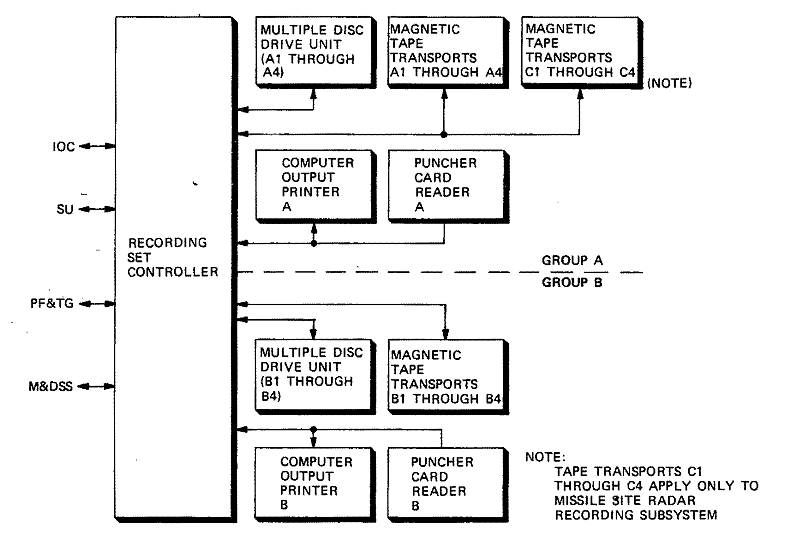
The RSS (Figure 11-5) provides the facilities for recording, storage, playback, and readout of DPS data and programs. The major functions of the RSS are to support installation of DPS equipment, support test exercises, and record data to provide a history of operation and maintenance events. In addition, the disc storage holds the program semi-permanently for system recovery.
As Figure 11-5 shows, the RSS operates with two identical sets of peripheral equipment. This permits it to be divided into two independent systems and thereby provides full recording capability for both DPS subgroups when the DPS operates in a partitioned condition at the PAR or MSR.
The major components of the RSS include a digital rack called the Recording Set Controller (RSC) and the following commercially-manufactured peripheral equipment: magnetic tape transports, multiple hardened disc drive units, punched card readers, and computer output printers. Bidirectional data transfers between the peripheral devices of the RSS and the CLC are via the RSC on a request-acknowledge basis.
Interface Subsystems
The SAFEGUARD System requires three interface subsystems to implement local and remote missile launch functions and intersite communications. Two of these, the Logic-to-Relay Converter and the Remote Launch Equipment, are used only with the MSR configuration to provide an interface between the CLC and the local and remote missile launch facilities, respectively. The other subsystem, the Data Transmission Controller, is used with the BMDC, MSR, and PAR configurations to provide a communications interface.
Logic-to-Relay Converter (LRC)30,31
The LRC provides the necessary pre-launch communication and conversion link between the logic circuitry of the Input-Output Controller (IOC) in the DPS and the relay circuitry of the Launch Preparation Equipment (LPE) in the collocated missile field at the MSR. This link provides for the software-controlled launching of SPRINT and SPARTAN missiles. The communication link between the DPS and the LRC is redundant throughout. The two LRCs used are functionally identical and interface with separate IOCs, but only one can be maintained on-line at a given time. The LRC is made up of the following units:
• The Missile Launch Equipment Controller (MLEC) which receives orders from the IOC in the form of 34-bit data words and interprets and forwards the data words, as logic levels, to the Missile Launch Equipment Adapter.
• The Missile Launch Equipment Adapter (MLEA) which converts the logic-level signals to relay control voltages, which constitute the missile orders that are transmitted to the LPE. Missile status signals, in the form of relay control voltages, are returned to the MLEA from the LPE. The MLEA converts the missile status signals to logic levels that are transferred back to the MLEC, where they are encoded into data words for transmission to the IOC.
• The Power Supply Set which supplies the dc voltages to operate the logic circuitry in the MLEC.
Figure
11-5. Recording Subsystem
Remote Launch Equipment (RLE)
This interface is covered in Chapter 9, which describes the SPRINT Missile Subsystem.
Data Transmission Controller Group (DTCG)32,33
The DTCG permits wideband and voiceband digital communication links between MSR and PAR configurations and between sites in the SAFEGUARD System. The DTCG has redundant equipment for partitioning purposes. It consists of: (1) Data Transmission Controllers, (2) Data Transmission Controller Adapters, (3) cryptographic equipment, and (4) data sets with associated data set adapters. The government furnishes the cryptographic equipment and data sets.
Maintenance and Diagnostic Subsystem (M&DSS)34-37
The M&DSS (Figure 11-6) provides a central facility for SAFEGUARD digital equipment maintenance. Only units allocated to the amber system are so maintained. The M&DSS contains the hardware and software necessary to perform or aid in:
• DPS initialization
• DPS recovery and loading
• Hardware fault detection and location
• Visual display of individual digital equipment status, including allocation (green or amber partition and test enabled/isolated) and summary error information
• Remote control and monitoring of dc power.
The M&DSS has two distinct facilities for running diagnostics. The primary one uses the M&D Processor (MDP) Group to execute diagnostic tests in a fully automatic, high-speed manner, with automatic interpretation of results; the other uses the M&D Console Group as a back-up for manually aided execution and interpretation of certain diagnostic tests. Each test facility is linked via logic in the M&D Data Controller and special hardwired data paths to all the digital racks in the DPS and to certain digital racks in the radar areas. Using these datapaths, M&DSS software can access each rack as required for DPS initialization, recovery, and diagnostic operations.
The diagnostic tests are executed on equipment placed off-line in the amber system. Monitoring of equipment in the green system is restricted to checking for correct output patterns.
System Readiness Verification (SRV) Subsystem38
The primary objective of the SRV subsystem is to verify the tactical readiness of the SAFEGUARD System, including its hardware, software, and personnel. To accomplish this, the CLC is partitioned into two independent systems (green and amber), and a combination of system tests and system exercises is performed. These assess site readiness by determining the availability and reliability of system hardware, the performance characteristics and functional capabilities of system hardware and software, and the proficiency of operating personnel, particularly in the Command and Control Display Subsystem (CCDS). Before these tests and exercises can be performed, the personnel must identify the elements to be verified, describe the processes (hardware, software, and procedures) involved, and state the expected results.
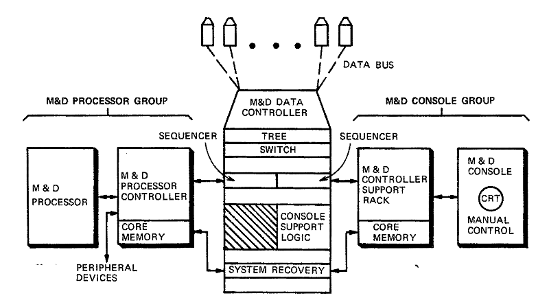
Figure
11-6. M&D Subsystem
The SRV subsystem contains the following elements:
• Exercise Data Processor (utilizing the amber partition of the CLC)
• Exercise Control Unit (a part of the DPS)
• Radar Return Generator (a part of the radar)
• System Exercise Console (a part of the CCDS).
Together, these elements form the exercise system in the amber partition of the DPS. In a system exercise, they drive the tactical system in the green partition of the DPS, causing the tactical system to respond as it would in a real engagement and thereby allowing evaluation of the dynamic system response and readiness.
The only part of the SRV subsystem in the DPS that has not been described is the Exercise Control Unit (ECU). This is a digital rack that provides the interface between the exercise system and the tactical system. It supplies the data and control paths necessary to: (1) monitor radar orders from the tactical system for the Exercise Data Processor (EDP) and inject simulated target information from the EDP into the tactical system via the Radar Return Generator, (2) monitor missile orders from the tactical system for the EDP and return simulated missile responses from the EDP to the tactical system, and (3) furnish communications between the exercise and tactical systems and/or between sites. It also interrupts all command paths to the missile launch stations to provide an extra measure of safety during system exercises.
Command and Control Display Subsystem (CCDS)39-42
The CCDS facilitates monitoring and directing the tactical operation and maintenance of the SAFEGUARD System.
The CCDS is composed of command and control equipments manned by personnel trained to perform tactical and maintenance operations. Tactical operations cover the weapon system response to the potential or actual threat to the protected area. Surveillance, target detection, target identification, and engagement activities are part of the tactical phase of operations in the CCDS area. Maintenance operations are concerned with maintaining each element in the SAFEGUARD System at its maximum availability by monitoring and coordinating maintenance for each subsystem.
Major operating equipment (Figure 11-7) used in the CCDS are:
• Logic Control Buffer — provides the interface with the CLC and the M&DSS
• Buffer Store — provides buffering to compensate for the difference between the data rates of the CLC and those required by the displays
• CRT Consoles — provide a dynamic interface between the human operators and the equipment (Figure 11-8 shows a typical CRT console)
• Console Logic Support Units (CLSUs) — include the circuitry required to generate the CRT console displays
• Non-CRT Consoles — provide operators with status information and controls to vary functions. With the exception of an end plate, they are electrically and mechanically identical to the Control Indicator Units associated with the CRT Consoles
• System Status Display Boards — provide status information on major elements of the SAFEGUARD System
• System Status Display Support Unit (SSDSU) — includes the circuitry required to generate the signals which drive the System Status Display Boards
• Teletypewriters (TTYs) — furnish communications between operating personnel and the CLC.
Other major operating equipments in the CCDS are:
• Nuclear Employment Authority (NEA) Equipment — consists of two Guided Missile Launch Enable Controllers (GMLECs) and a Guided Missile Launch Enable Group (or NEA rack) in the Combat Operations Center at Cheyenne Mountain and one NEA rack at the Missile Direction Center (MDC) in Grand Forks (see Figure 12-3 in Chapter 12)
• Launch Enable Equipment (Figure 11-9) — consists of two Launch Enable Message Controllers (LEMCs) and one Launch Enable Message Transmitter (LEMT) in the Ballistic Missile Defense Center, and a Launch Enable Message Receiver (LEMR) with a Launch Enable Transmission Set (LETS) at the collocated missile farm and each of the remote missile farms.
The GMLECs control a coded message generator to release or withdraw authority to expend SPRINT and SPARTAN missiles. The generator can also produce a test message to check the major parts of the NEA system. The NEA rack at the MDC decodes the message and presents status independently to hardware (wall displays and Missile Monitor Test Console) and through the status unit to the tactical software, which drives the CRT displays. Redundancy is used when required in the NEA system design to assure reliability. Considerable fault indication and fault isolation circuitry also is included.43, 44
The LEMCs control a coded message generator in the LEMT, which provides either an enable message or a disenable message to the Launch Enable system. A test message also can be generated for system checkout. The LEMT provides status signals to the CPS and LRC to indicate which message is being transmitted. The coded message is received by the LEMR, checked for errors, and slowed down for transmission through the LETS to the electromechanical Launch Enable Coded Switch (LECS) in each missile cell. The LECS has functional contacts, which interrupt the High Energy Firing Unit charge and trigger circuits and one of the Launch Order signals when the system is in the disenabled or safe condition. When in the enabled position, these paths are completed. The LECS also has a status monitor contact that indicates to the LEMR which state resides in the switch. These status signals are summed and fed back to the DPS and LRC.
The LECSs are electrically recodable from the LEMR by the Launch Enable Recode Test Set. Redundancy is used where required in the Launch Enable design to assure a high degree of reliability. Considerable fault indication and fault isolation circuitry also is included.45,46
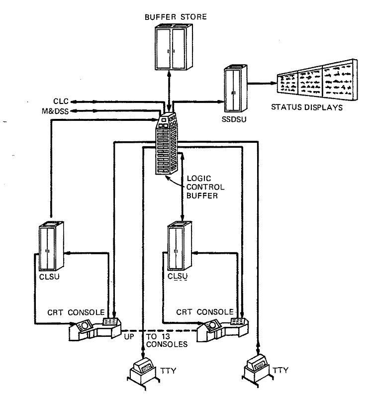
Figure
11-7. Command and Control Display Subsystem — Console, Wall
Display, and Teletypewriter Interface
Figure 11-8. Typical CRT Console with Control Indicator Unit
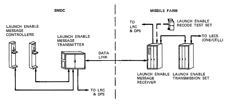
Figure 11-9. Command and Control Display Subsystem — Launch Enable Interface
One of the primary reasons for developing a parallel, modular computing system for SAFEGUARD is the potential for high performance. Besides having high availability, a multiprocessor organization possesses a great deal of reserve power, which, when applied to a problem with the appropriate degree of parallelism, can yield high performance. This type of problem is associated with a radar tracking system and must be solved in real time.
In a multiprocessor system, the processors gain access to main storage according to a priority rule. The rate at which each processor executes instruction depends, therefore, on the severity of this queuing at main storage. Throughput is defined as the number of instructions of a particular instruction mix executed per second by n processors.
Adequate performance or throughput of a parallel processing system depends on several hardware factors, which include the speed of the processor; the speed of program store, including its priority circuit; the total number of processors relative to the total number of independently addressable program stores; and the number of instructions executed per memory word fetched. From a software viewpoint, the distribution of programs and data sets within the modular memory and the instruction mix of the particular programs in execution also are important factors, which directly affect throughput.
Since variable store queuing, in general, is less than that at program store, its effect has been eliminated in the throughput data presented here. This has been done by dedicating a separate variable store rack to each processor for experimental studies.
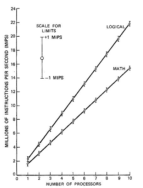
Throughput data has been gathered using multiprocessor hardware with as many as ten processors. Benchmark programs, which provide varying instruction mixes, have been used. Four instruction mixes were selected for testing. The NOP mix, consisting of no-operation instructions, defines an upper bound on throughput. The LOGICAL mix is a representative mix similar to CLC operating system code that might be executed during real-time operations. The MATH mix is also a representative mix, since it is a portion of the cosine subroutine from the CLC operating system. The JUMP mix consists exclusively of jumps and represents a kind of lower bound on throughput.
Figure 11-10 shows the effect of requiring all processors to execute from one program store. The number of instructions executed per second increases with the number of processors until the program store is returning instructions as fast as it can. Throughput levels off when this point is reached, and a further increase in the number of processors does not increase throughput.
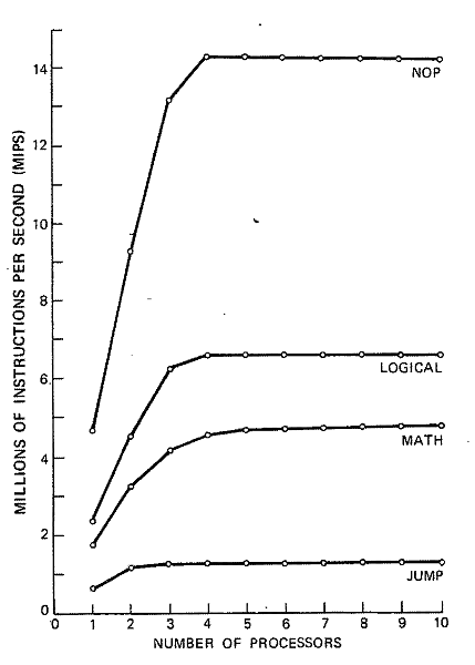
Figure
11-10. N Processors Executing from One Program Store
Figure
11-11. N Processors Executing from N Program Stores
Figure 11-11 shows the effect of providing an equal number of processors and program stores. For this case, the number of processors and program stores is incrementally increased from one to ten. The program stores are not dedicated to a processor on a one-for-one basis, but their access by the processors is randomized such that several processors may be attempting to read from the same program store at once. Hence, some reduction in throughput due to queuing is expected. The effect of queuing is small for one to ten processors; Figure 11-11 shows that throughput increases linearly with the number of processors. Data is shown for the LOGICAL and MATH mixes only.
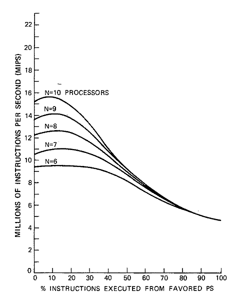
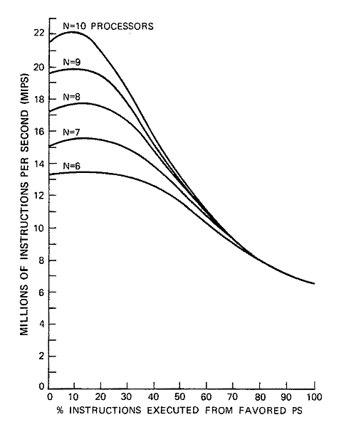
Figure 11-11 shows an even distribution of memory access over all program stores. To determine what happens to throughput for an unequal workload distribution, a series of runs were made for both the LOGICAL and MATH mixes where the number of processors was kept equal to the number of program stores with one important difference; one of the program stores was selected as à "favored" program store and its fraction of total instructions executed was varied from 0 to 100 percent while the remaining program stores shared the remaining workload equally. Figures 11-12 and 11-13 show the results for the six to ten processor cases. The curves represent throughput as a function of the "favored" program store. Zero percent means ten processors are executing out of nine program stores. Note that throughput is highest when the "favored" program store shares equally in the workload.
The curves of Figures 11-12 and 11-13 show the sensitivity of throughput to an equal distribution of the workload in memory. For instance, if one considers a 10-percent reduction in throughput to be serious, the above curves show for the seven-processor case that a single program store can have almost 40 percent of the workload without a serious reduction in throughput. For the ten-processor case, the corresponding number is approximately 25 percent. Therefore, as long as the workload is not too unequally distributed, the dependence of throughput on workload distribution should not be critical. Throughput dependence on more than one program store's having more than an equal share of the workload has not been investigated.
Figure
11-12. Unequal PS Loading, LOGICAL Mix
Figure
11-13. Unequal PS Loading, MATH Mix
The following major technical innovations were made during the development of the DPS.
A Multiprocessor, Partitionable System with (n+1) Redundancy
The CLC represents the first practical application of the multiprocessing concept to a large-scale computing system. In this modular design, as many as 10 processors and 2 Input/ Output Controllers share as many as 32 memory racks. The units are interconnected by a flexible switching network that facilitates partitioning the system into two independent computers. Partitioning can be controlled by software, and complete reconfiguration can be accomplished in less than 1 second.
Although it may have been possible to design a single processor with adequate performance, the CLC is a multiprocessor machine for three reasons. First, a single processor sufficiently powerful would have been a complex machine, difficult to design, and difficult to get working. Second, a single-processor system would not have been expandable; if a more powerful machine were later needed and none were available, major software changes would have been required. Also, multiple processors satisfy a wide range of processing requirements, including smaller applications. Finally, the multiprocessor design increases availability because processing can continue even if some processors have failed.
The processor is the most important element in establishing the real-time computing capacity of the CLC, so the design of a high-speed processor was a primary goal. Each processor contains three control units that operate asynchronously with respect to each other. Timing within each control unit is overlapped to some degree so that more than one instruction can be in execution. The use of high-speed arithmetic algorithms and associated logical implementation has been exploited advantageously to increase the flow of operands through the arithmetic sections. The resulting processor design can execute successive fixed-point add operations on full-word 32-bit operands at an average rate of 4.15 million per second. Results with more than one processor are given in Comparison of Performance Objectives and Results.
A multiprocessor design hinges on its storage design. A number of possible strategies are available to handle the necessary references of the multiple processors to main storage. The first strategy used in the design is the splitting of main storage into two independent portions, called program (or instruction) store and variable (or operand) store.
To further increase the data flow rate between processors and main storage, program and variable store are further subdivided into modular groupings. Variable store is organized as 16 independent racks, with an independent data path from each rack to each of the processors. Since queuing is heavier at program store than at variable store, program store is organized as 32 independent modules with an independent data path from each module to each of the processors. Processor addressing is interleaved between two modules; that is, the address structure is arranged so that adjacent program store words reside in two separate modules.
The memory module cycle time of 500 nanoseconds and the double-word size of 64 bits provide a memory bandwidth greater than that required for maximum performance of a single processor. Each program store and variable store rack holds 16,384 64-bit words. There are four parity bits associated with each memory word.
The CLC can be partitioned into two independently operating computers, each capable of executing its own job stream. By convention, these two partitions are called green and amber, with green usually designating the larger of the two fractions. However, since the computer is composed of a number of modular elements, the boundary between green and amber is almost completely flexible. In fact, all elements can be brought into the green partition to operate as a very large multiprocessor computer with as many as ten processors sharing the job load. As a further degree of flexibility, some elements (such as memory elements) may be placed into a shared green/amber state, in which they are available to both partitions simultaneously. Finally, an element may be defined as neither green nor amber but isolated. This state is necessary to remove malfunctioning elements without shutting down the entire system.
It is even more significant that partitioning is under program control. Further, the control logic for effecting partitioning is redundant. A fundamental asymmetry allows the green partition to have priority over the amber partition. The partitioning logic may be placed into a state whereby a master/slave relationship exists between the green and amber partitions. Control software residing on the green partition may alter the partitioning of the system at any time. The amber or slave partition can in no way alter the partition boundaries.
Early fault-tolerant systems employed 100-percent redundancy through use of a complete standby system; that is, the system required to support the full workload was duplicated, with data processing proceeding in parallel on each system. This organization is conceptually simple and, upon detection of a failure in either system, the other system can carry on the data processing workload.
The multiunit system approach to high performance can provide high system availability without the need for costly, complete duplication. The "n+1" redundancy approach has reduced the amount of equipment added for redundance and for system exercise to a fraction of that required for a complete standby system.
A Versatile and Workable M&D Approach
The SAFEGUARD System's specific tactical mission is extremely brief compared to the life of the system. Once a tactical mission has begun, the M&DSS ceases fault isolation and repair; if serious failure occurs, system recovery must automatically execute, using its built-in redundancy. Therefore, the fault detection and isolation features of the M&DSS are directed toward maximizing system availability, which is the probability that, at any point in time, a complete set of fault-free DPS resources exists for a mission.
The M&DSS contributes to maximizing system availability in two ways. First, M&D tests are periodically run on critical DPS equipment to supplement real-time fault detection methods in minimizing the mean-time-to-awareness of hardware faults. These tests are automatically scheduled by real-time software in the green partition and the test requests are sent to the M&DSS over a special interface through the SU. In this way, every processor in the DPS is switched into the amber partition and tested once every hour; the complete amber partition is tested once each hour; and the green IOC with its slaved peripheral controllers is switched amber and tested once every four hours. The M&DSS passes test results back to green system software again via the SU interface.
Second, and more important, the M&DSS minimizes the mean-time-to-repair of faulty racks by rapidly identifying a minimum set of replaceable or easily repairable modules in which the fault is located. These fault isolation functions may be initiated in response to fault symptoms detected either in real time or during the non-real-time scheduled tests described above. In either case, fault isolation takes place with the failed rack isolated from the rest of the DPS.
The M&DSS accomplishes this goal through the unique integration of two significant maintenance concepts. First, it uses a special two-way maintenance data path into each DPS digital unit which bypasses normal data paths. Second, it uses a small general-purpose computer, dedicated to system testing, to apply tests over the maintenance paths and interpret test results.
The communication interface between the green partition SU and the M&DSS provide a rapid and flexible means for bringing maintenance resources to bear on any DPS fault indication. Nonetheless, until a specific faulty rack has been identified, the particular response to be made to any given fault indication often involves judgements based on the total status of DPS resources. Thus, normal SAFEGUARD maintenance operations involve a significant degree of manual interaction. In general, two primary maintenance management functions are performed manually:
1. Monitoring and response to overall system status as reported by green system real-time software and hardware displays
2. Direct control of maintenance testing; the M&DSS will not honor any scheduled test request unless manual "permission" is granted, any test in progress may be manually aborted, and alternate tests may be requested via green system software and the SU interface.
Experience has demonstrated the fundamental power and flexibility inherent in the primary M&DSS feature, the extensive maintenance data interface with the entire DPS, in concert with the general-purpose computing capability of the M&D Processor. Just as encouraging, however, has been the performance of a set of extended M&DSS capabilities developed during the early phases of installation and operation, before the widespread availability of M&D tests.
Central to the extended capabilities of the M&DSS are the Digital Unit Exerciser (DUXs). One such program exists for each DPS rack type. Each DUX program facilitates controlling functional operations of a rack on a macroscopic level and "dumping" the contents of individual registers or groups of related registers within the rack. In actual hardware operation, DUXs have been used primarily to provide manual interaction, via the M&DSS, with a set of real-time programs originally developed to verify the complete functional capabilities of the DPS. Data currently being gathered at SAFEGUARD sites show that this mode of fault detection and isolation is still important. The various DUX capabilities also have provided an extremely powerful means of aiding system software debugging by allowing dumps and snapshots of otherwise inaccessible DPS registers without perturbing the very condition being probed. This capability has been used extensively throughout the SAFEGUARD software development.
A Processor Unit with a Basic Operate Time of 200 nsec
When the NIKE-X development began, operate speeds in this range were in advance of the state of the art. A demonstration of a prototype unit operating at this speed was conducted successfully at UNIVAC in 1965, and the first full-scale model was successfully operated in 1967.
A Coupled Film Memory with a 68-bit Word Length and 200-nsec Cycle Time
Memory speeds in this range were specified initially to match the processor design speed. During the early days of NIKE-X, laboratory models and small memories had achieved this speed, but the challenge of mass-producing large, fast memories remained. This challenge was met, and 200-nanosecond coupled film memories were manufactured successfully for the Whippany and the Meck Installations.
A System Readiness Verification Subsystem for Realistic Simulation without Relying on Processor Self-Checking
Experience with the Analog Tactical Environment Simulator in the Meck system and a 1968 study resulted in the exercise concept for SAFEGUARD. This concept uses the amber system CLC working through the ECU interface to drive the green system CLC or the Missile Subsystem in a simulation mode, and working through the Radar Return Generator to inject targets into the receiver to check system operation in its entirety. This concept permits the green system software to remain virtually unmodified in the exercise mode. The approach has been proven successful in system operation to date.
A Quick-Reaction, Remote-Controlled Nuclear Safety System
Previous Army nuclear safety systems relied on close proximity of the weapon to the officers responsible for weapon release. In addition, the time required to release SAFEGUARD had to be shorter than any previous system reviewed by the Nuclear Weapon System Safety Committee. The Launch Enable system, as designed, provides safety and remote release capability.