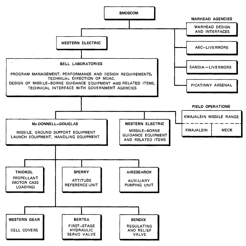
Figure 10-1. SPARTAN R&D Organizational Structure
The role of SPARTAN in SAFEGUARD is to intercept ballistic missile targets at long range, with a large payload, in the exoatmosphere. The missile finally deployed at Grand Forks, North Dakota resulted from an extensive R&D effort which began in 1955 during the NIKE-ZEUS program. As requirements changed, SPARTAN evolved from a single-stage, hypersonic, winged antiaircraft missile, which was never built, through three configurations of antimissile missiles (DM-15A, B, and C) to the present design. Originally designated DM-15X2 (ZEUS-NIKE X), this missile was named SPARTAN in January 1967.1 SPARTAN is similar to the NIKE-ZEUS DM-15C configuration, modified to increase motor performance, improve missile guidance, and increase warhead yield.
In January 1965, a nine-month study of the role of ZEUS in the NIKE-X System concluded that a ZEUS-type interceptor with a high-yield nuclear warhead would furnish a large-volume exoatmospheric kill capability against threats of interest. In March 1965, Bell Laboratories was authorized to proceed with Phases I and II. of the R&D: defining the ZEUS missile subsystem based on NIKE-X system requirements and design trade-off studies, planning the development program, and completing the preliminary design.
Phase III of the R&D program began in October 1965 as formal design started and specific system and design trade-off studies continued.2 The principal parts of the program were (1) a 29-month detailed engineering design, hardware fabrication, and ground test phase and (2) flight tests at Kwajalein and Meck Islands. An extensive functional and environmental test program, which included several months of system integration testing in the laboratory, was carried out before the first flight test in March, 1968 at Kwajalein. The R&D missile configuration reflected the basic approach of "do it once; do it right" —the projected tactical design was built into the first flight missile and interim test missile designs were avoided. Thus, the flight test data on each major component were directly useful in the final design. As a result, the missile development test program at Kwajalein consisted of only 15 missile flights. The first SAFEGUARD System flight test with a SPARTAN missile launched from Meck Island took place in April 1970. Twenty SPARTAN missiles were launched during the SAFEGUARD System test program, which was completed in June 1973. After that, five production missiles were flight tested during the Product Assurance Verification Test (PAVT) program.
As shown in Figure 10-1, many agencies, organizations, subcontractors, and suppliers took part in the development of SPARTAN.

Figure
10-1. SPARTAN R&D Organizational Structure
MAJOR CHALLENGES AND INNOVATIONS
Because it evolved from earlier designs, developing SPARTAN did not require new technological breakthroughs. However, it did take determined and innovative engineering to produce a manufacturable design that functioned in the imposed environments with the specified availability and reliability. Several facets of this effort were:
1. Establishing a high reliability component program. Early in the development it seemed essential to establish a component procurement program under the strictest reliability procedures. The program included a Bell Laboratories-approved list of high reliability parts from qualified vendors. It also included procurement specifications designed to ensure reliability that far exceeded the MIL specifications commonly used by the military. Each SPARTAN missile contains roughly 10,000 high reliability electronic parts. This emphasis on ultra-high reliability contributed to superior SPARTAN performance during the Meck flight test program.3
2. The missile structure and all its subsystems, including electrical components, had to withstand severe nuclear effects. The extensive program that achieved and assessed nuclear hardness has been thoroughly documented.4 For more information on this program, see Chapter 6.
3. Another SPARTAN innovation was an ablator, which is lightweight and applied with spray heads while a missile section is rolled on its axis. During R&D flight tests at Kwajalein, the ablator proved it could protect the missile from the extreme heat induced by atmospheric flight. Special instruments were imbedded in the ablator to determine the depth and rate of ablation.
4. The Missile Guidance Set (MGS) developed for SPARTAN is essentially the same as the SPRINT MGS. It uses extensive foaming of subassemblies and a preload arrangement to ensure proper operation during severe shock, vibration, and noise. The MGS has a three-channel receiver, which monitors the signal received by three equally spaced pairs of missile antennas and automatically switches the beacon transmitter pulses to the antennas with the strongest received signal. This transmitter switching feature, coupled with a hard limiting, instant response, intermediate frequency amplifier, lets the MGS detect and decode signals during the rapid fading caused by attenuation from missile plume and plasma sheath.
5. At first, a design based on discrete components was developed for the Launch Preparation Equipment (LPE). Later in the SPARTAN development cycle, Integrated Circuit (IC) technology which had become well proven, was shown to be more suitable for the LPE, especially from the standpoint of production costs. An Integrated Circuit LPE (ICLPE) design was introduced and proved to be highly reliable during flight tests at Kwajalein.
6. The Sperry fluid-sphere gyro in the SPARTAN attitude reference unit was the first application of this unique device in a major system. The concept of sensing pressure differentials between a rotating fluid and its container produced a device more reliable than the conventional gyro, which senses gimbal axle displacements with relatively delicate sensors.
7. Other innovations in SPARTAN included a sealed hydraulic control system and a quartz nose cap. The hydraulic system was found-to be very reliable during storage and in-flight operation, while the nose cap withstood worst-case natural environments.5
SPARTAN Subsystem Operation
The SPARTAN subsystem consists of high-performance interceptor missiles, controlled by ground radar and armed with nuclear warheads, plus associated ground support and launch equipment.1 The missiles are deployed in a launch area near the Missile Site Radar (MSR) and emplaced in underground cells equipped with environmental control, testing, and monitoring equipment. Control and status -monitoring equipment are linked to the Missile Site Control Building (MSCB).
The three-stage, solid-propellant missile can intercept ballistic missiles at extremely high altitude and long range. The third-stage motor is normally used late in flight to achieve more accurate intercepts and to orient the warhead. As an option the motor can be used early in flight to extend SPARTAN'S maximum range. The Missile Site Data Processor (MSDP) command guides the missile via the MSR link, and an onboard transponder generates short beacon pulses to help the MSR track the missile.
At launch, a command from the MSDP ignites the SPARTAN first-stage motor and the motor lifts the missile from its underground cell. Ballistic flight is used during first-stage motor burning. The fixed first- and second-stage fins and the locked third-stage control surfaces keep the missile aerodynamically stable. At the end of first-stage burning, the second stage is ignited and its thrust forces separate it from the burned-out first stage. During second-stage flight, four movable control surfaces on the third stage aerodynamically steer the missile and control its roll rate.6
The second stage burns out within the atmosphere after approximately 25 seconds of missile flight, and the missile glides out of the sensible atmosphere. An MSDP command via the MSR can ignite the third-stage motor at any time after the missile leaves the atmosphere. Prior to intercept, the burned-out second stage is separated from the third stage, which contains the warhead. Skin-cutting ordnance separates the two stages shortly after the third-stage motor ignites,7 and ground commands control both the ignition and separation. Nozzles in the rear edge of the third-stage control surfaces vector the exhaust of the third-stage motor to control exoatmospheric reaction.
To maximize warhead efficiency, commands from the ground properly orient the missile centerline with respect to the predicted intercept point before the third stage burns out.8 The missile is then spin-stabilized to maintain this orientation until intercept.9, 10
Missile
SPARTAN's first- and second-stage motor cases are built of high-strength steel (see Figure 10-2). Monocoque aluminum construction is used in the first- and second-stage cylindrical guidance section and in the two-piece conical control section. There are three antenna strakes at the forward portion of the warhead section and three additional antennas mounted on the nose fairing.
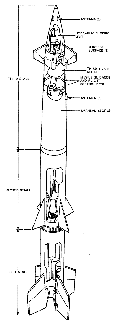
Figure
10-2. The SPARTAN Missile
Ablative materials on appropriate sections of the missile skin dissipate boundary layer heat and limit internal missive temperatures. The three materials used are Teflon [*], phenolic refrasil, and sparesyl.
[* - Trademark of E. I. DuPont de Nemours.]
Teflon sublimes at high temperatures and is, therefore, used on the nose fairing and on the third-stage nozzle impingement pads.8 Phenolic refrasil is used in the third-stage fin area and on the leading edges of the second-stage fins. The remaining surfaces of the second and third stages are insulated with a lightweight albator called sparesyl. The first stage does not require insulation.
The first and second stages are essentially propulsion units with stabilizing fins. The third stage contains the warhead section, missile guidance set [*], flight control set,11 hydraulic pumping unit, third-stage motor, and four control surfaces (thrust vector control).
[* - This guidance equipment also is used in the SPRINT missile. See Chapter 9 for a description of this unit.]
The missile guidance set receives steering orders from the ground and applies them to a flight control set to move the control surfaces through hydraulic servos.12 Since the ground-based system elements do not sense missile attitude, orders from the ground are sent in earth coordinates. These orders are then converted to missile coordinates by the stable reference system in the flight control set.13 The missile guidance set receives discrete commands, decodes them, and sends them to appropriate subsystems. These commands separate the third stage, start the third-stage motor, and control various warhead functions.
The SPARTAN Hydraulic Pumping Unit (HPU) is shown in Figure 10-3. The gas generator, consisting of an initial and terminal grain, sends a flow of gas to the turbine. The flow rate depends on propellant formulation, chamber pressure, grain temperature, and grain geometry. The hot gas shutoff valve, which transfers from initial to terminal grain operation when required, functions in one of two modes of operation: the dwell mode, in which the initial grain has burned out before the valve is actuated, and the overlap mode, in which the valve is actuated when the initial grain is still burning. The operating gas pressure is controlled by the burn-rate control valve.
Under steady-state conditions, oil flows from the pump to the accumulator, through the accumulator relief valve, then to the reservoir, and back to the pump. The accumulator is pre-pressurized at initial-grain ignition with nitrogen released by the accumulator explosive valve.
Under transient conditions (when the control surfaces are active), the accumulator furnishes oil to the control surface actuators via the regulator valve. The reservoir receives the return flow from the actuators. Under these conditions, turbine speed will vary as necessary to restore and maintain steady-state operating pressure in the accumulator.
Launch Station
The SPARTAN launch station (Figure 10-4) consists of a steel-lined launch chamber, exhaust duct, Launch Preparation Equipment Vault (LPEV), the Mechanical and Electrical Equipment Vault (MEEV), and the launch area antenna.14 The launch station provides long-term storage for the missile, tests and launches it, and protects it and its launch and test equipment from natural and battle-induced environments.15,16
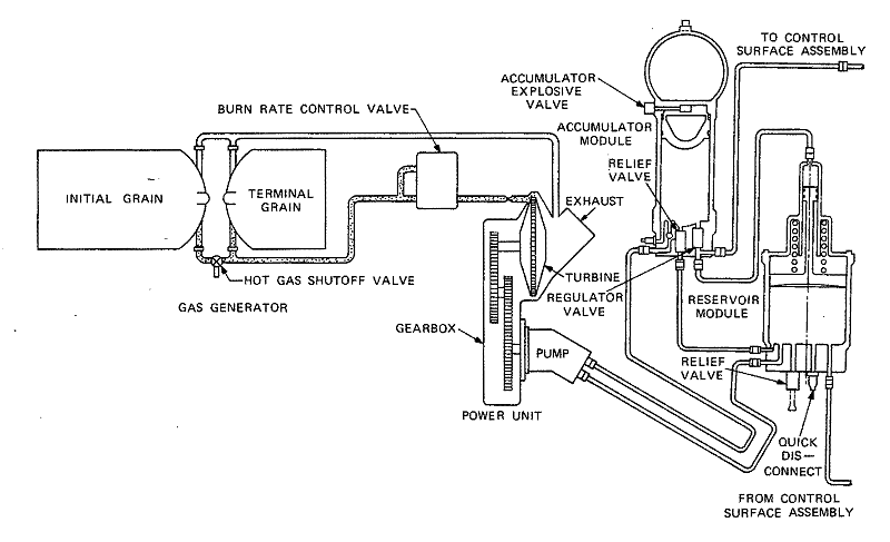
Figure
10-3. SPARTAN Hydraulic Pumping Unit Assembly
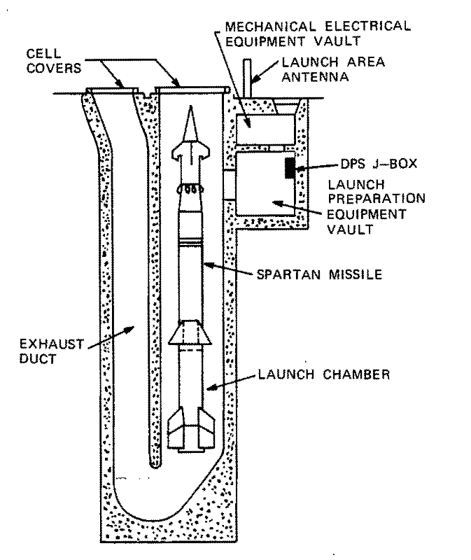
Figure
10-4. SPARTAN Launch Station
The launch chamber contains a launch rail to support the missile in a ready-to-launch attitude. Associated with the launch rail is the mechanism for extracting the missile umbilical, the forward cradle capture equipment, the first-stage igniter mounting, and the High-Energy Firing Unit (HEFU).17 A shock-isolation system in the launch rail attenuates nuclear or earthquake ground shocks to less than 1 g.18, 19
The launch chamber and exhaust duct are protected by two 2-piece cell covers (Figure 10-5). The covers, each half weighing 4800 lbs, are held closed by bolted plates. During launch, a linear-shaped charge severs the plates and the cell covers are moved rapidly to an open position by a piston and cylinder attached to each cover half. Each cylinder is pressurized by a hot-gas generator ignited by dual squibs.
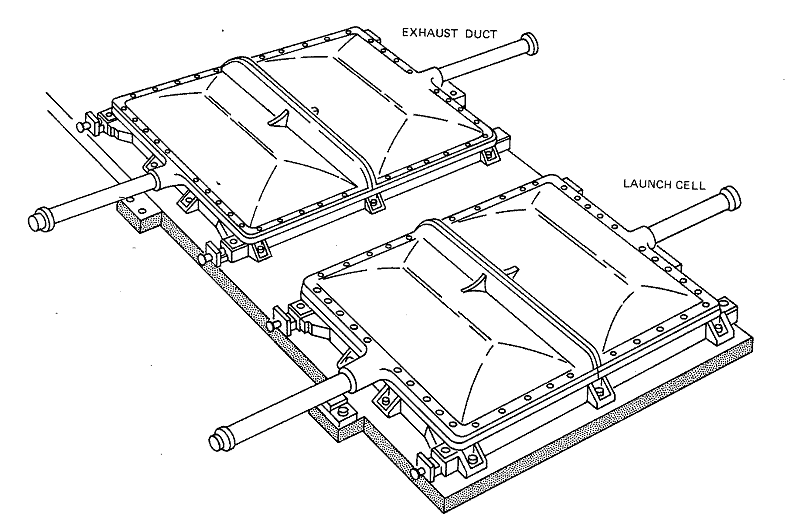
Figure
10-5. Launch Cell Protective Covers
The MEEV and LPEV are located on the side of the launch station.20 The MEEV, which is above the LPEV, houses the launch station heating and air-circulation equipment and is reached through a submarine-type hatch cover. Air in the launch station is purged through the MEEV. The LPEV is entered through a hatch from the MEEV, and the launch chamber is entered from the LPEV through a blast door. The underground location and configuration of the LPEV shield it from nuclear and RF radiation.21
The Environmental Sensor Kit (ESK) is housed within the LPEV. In conjunction with remotely placed sensors, it monitors launch chamber and LPEV temperature, humidity, and water levels. An out-of-limits indication in an ESK sensor will generate a minor alarm which is transmitted to the MSCB via the Data Processing System Junction Box (DPS J-Box).
Launch Preparation Equipment Set
The Launch Preparation Equipment Set (LPES), Figure 10-6, is composed of the Launch Preparation Equipment (LPE), DPS J-Box, and High-Energy Firing Unit (HEFU). All elements of the LPES except the HEFU are inside the Launch Preparation Equipment vault; the HEFU is at the bottom of the launch cell. The LPES is the functional link between the Data Processing System (DPS), the MSR, and the cell-emplaced missile. It prepares the missile for launch by testing the missile systems and monitoring critical missile and launch cell support equipment during the preparation period, ready period, and launch sequence. It also supplies the missile with ground operating power for all tests until the missile is switched to internal power during the launch sequence. In addition to its power and missile checkout function, the LPES, in conjunction with the DPS, can execute, interrupt, and recycle a preparation/RF test request at any time before the launch sequence starts.
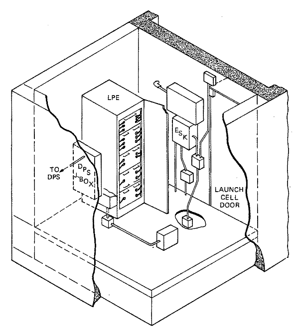
Figure
10-6. Launch Preparation Equipment Set (Tactical)
Nuclear weapons can be used only upon presidential authority, and SAFEGUARD is released through the North American Air Defense Command (NORAD) at the Cheyenne Mountain Complex. The release information is transmitted in coded form over a data link to the Missile Defense Center (MDC), where the message is decoded and the contents are placed on a system status display.
A second message is then originated within the Launch Enable (LE) equipment as the first part of a chain of events that launches a missile or tests the system. The elements of the second message pass through the launch enable message transmitter to the launch enable message receiver and then to the launch enable transmission set. Finally, the message is fanned out to Launch Enable Coded Switches (LECSs) mounted in each of the missile launch cells. Receipt of a properly coded launch enable message by the LECS permits missile launch orders generated by the DPS to initiate the launch sequence. During the launch sequence, the LPES generates signals that activate the missile launch order squibs, set the remote arm switch, activate the cell covers, and charge and trigger the HEFU for the first-stage ignition.
Ground Support Equipment
The SPARTAN Ground Support Equipment (GSE) consists of field checkout and maintenance equipment, missile-handling equipment, and shipping containers. Some of the major items are:
1. The Fault Isolation Test Set (FITS) is used to isolate failures and to verify LPE operation when a major alarm is received from a launch station. The FITS first tests the LPES to isolate the fault to either the missile or the LPES. Faults in the LPES are isolated to the drawer level of the LPE and to the unit level of the DPS junction box. Maintenance crews replace the faulty units and the FITS/LPE test is repeated to verify that the fault has been corrected.
If the LPES works properly, it is assumed that the missile is at fault. First, maintenance personnel enter the launch cell and disarm the missile.22,23 Next, they remove the guidance/control section to gain access to the warhead section. The FITS and the LPE are used to test the warhead section functions. If a fault is detected in the warhead section, crews remove it and send it to the on-site warhead building for further testing.24,25 If no fault is detected in the warhead section, the guidance/control section is presumed to be at fault and a spare section from the Universal Missile Building (UMB) is installed. Fault correction is then verified by the LPE.
2. The Third-Stage Test Set (TSTS), Figure 10-7, is used in the UMB and warhead buildings to functionally test the guidance section, control section, and warhead section interfaces. It can test third-stage ignition circuits, isolate control section faults, and isolate warhead section faults.
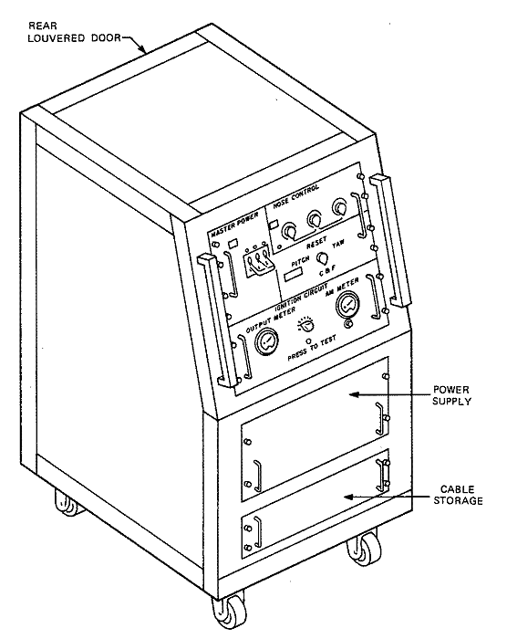
Figure
10-7. Third-Stage Test Set
3. The maintenance van, Figure 10-8, can transport the spare LPE drawers, the FITS, and maintenance tools. The maintenance van has a shelter which is deployed over the entrance to the MEEV to allow access while protecting the missile from natural environments (rain, wind, and snow).26
An overhead electrical hoist in the van removes and replaces LPES components and transfers test equipment between the van and the LPEV.
4. The missile-handling equipment includes all of the necessary fixtures, loading beams, and slings for assembling missiles at the UMB and at the launch station. It also includes the Universal Transporter Loader (UTL) shown in Figure 9-7 of Chapter 9.
The UTL is a self-propelled vehicle that transports missile sections and loads them into cells. A weather shield protects the cells from natural environments during missile-handling operations.
Propulsion
Development of the SPARTAN propulsion system started in April 1966. The effort was not extensive because the objective was to use NIKE-ZEUS technology as much as possible.
SPARTAN'S first-stage motor is almost identical to the NIKE-ZEUS DM-15C motor. The first-stage pressure-vessel design is identical except for a change from special sandwich-rolled 4340 steel to cold-rolled 4340. This change resulted from improvements in steel-rolling techniques, which allowed use of the more economical cold-rolled sheet while retaining high quality and close dimensional tolerances. Other hardware changes were minor, and DM-15C's grain geometry was carried over to SPARTAN. SPARTAN also had an improved case insulation and a new propellent formulation that was common to the first and second stages.
The SPARTAN second-stage motor is a reconfigured DM-15C first-stage motor. The steel motor case is the same, except for the interstage connections and a larger port in the head end to accommodate the igniter. Both the propellent formulation and the grain configuration are new. A Carboxyl -Terminated Polybuta-diene (CTPB) propellant with 87 percent solids was developed for the first and second stages. Since the Thiokol Chemical Corporation, which had the subcontract for the propellant, had extensive experience with the binder system and had done considerable research and development in high-total solids, a basic propellant formulation could be selected. The proper burning rate was reached and ballistic reproducibility was achieved by tailoring the oxidizer and fuel particle sizes, optimizing their distribution, and determining the proper amount of burning-rate catalyst. Seven full-scale second-stage motors and one first-stage motor were all successfully static-fired before the first flight test.
The third-stage motor design is the same as that used in the NIKE-ZEUS DM-15C missile.
After the first successful missile flight, the propellant-liner interface was found to be separated in the forward opening of the second-stage motor. This problem occurred in several motors and reappeared after the material containing the original separations was trimmed out. The difficulty was first diagnosed as a tooling problem, but visible head-end separations and/or subsurface defects kept occurring after tooling changes. The problem was solved for the remainder of the development program by removing propellant from the area where separations were found and replacing it with a cast-in-place burning-inhibitor boot.
Near the end of the production program, massive propellant separations appeared in some second-stage motors in the same forward dome area behind the boot. The defect appeared only in some but not all of the motors cast from a particular lot of raw materials. Since the defect was confined to one materials lot, and since none of the motors from that lot were needed to meet the reduced deployment requirements, it was decided by the Ballistic Missile Defense System Command (BMDSCOM) that no funds should be provided to further isolate the problem. During this investigation, the effects of migration of the burning-rate catalyst were evaluated. It was found that the catalyst did not concentrate enough to impair the physical properties of the propellant-liner interface when the liner thickness was correct and proper cure time was used.
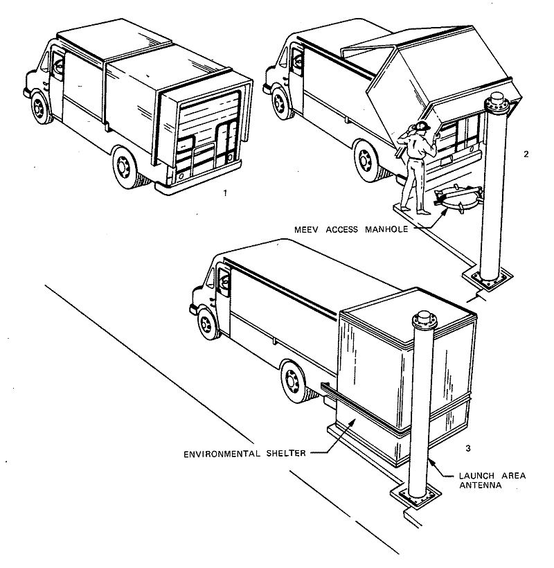
Figure
10-8. Maintenance Van Deployment Sequence
One SPARTAN development flight, KT-05, failed in November 1968 because of propulsion problems. Although the exact cause could not be pinpointed, it was deduced that the second-stage nozzle exit cone bent with respect to the nozzle entrance structure, perhaps because of vibration, shock, or acoustic noise, and allowed gas to leak through the insulation. The exit cone support structure was stiffened, and there were no further problems.27
In addition to SPARTAN motors used in other development tests, three sets of motors were given road tests, drop tests, and temperature cycling tests, in that order.28 One set of motors was ground-fired and the remaining two sets were flight-tested. All motors performed normally.
Missile-Borne Guidance Equipment
Development of dual-frequency Missile-Borne Guidance Equipment (MBGE) began early in the NIKE-X program. The MBGE mounted in both SPARTAN and SPRINT missiles was designed to operate with signals from either the Multifunction Array Radar (MAR) on L-band or the Missile Site Radar (MSR) on S-band. The SPARTAN MBGE consists of a missile guidance set, six antennas, and interface cabling. At the outset, it was decided to design deployable hardware and not to go through an R&D phase followed by a redesign for production. This approach saved many hours of dead-end engineering.
After the MGS subassemblies (receiver, transmitter, decoder, and power supply29) were breadboarded, two prototypes were built. One, which consisted of foamed subassemblies, was used for shock, vibration, and centrifuge testing, while the other was used for electronic testing. Both units were built with electronic components purchased with the special high-reliability procurement specifications. The high-reliability program started at the beginning of MGS development to ensure that a quality product would be deployed. To achieve an extremely low failure rate during MGS life (storage and flight), the number of component types on the approved usage list was minimized. Stringent component specifications weeded out weak products. In many instances, specifications included component burn-in tests. Before a component was authorized for the approved usage list, the vendor's production lines were extensively qualified, and a single source was established for each component type during the R&D program. The approved usage list of electronic components became a requirement for SPARTAN and SPRINT missile-borne hardware and launch preparation equipment.
While the MGS was being developed, L-band and S-band missile antennas were designed and fabricated. S-band antennas, which are used on both SPARTAN and SPRINT, must withstand the shock and vibration of flight and the extreme heat generated on the missile skin. To optimize antenna coverage, various missile-mounting geometries were tested on scale models and antenna pattern measurements were made later on full-scale sections.30 A combination of three antennas forward and three midway down the missile proved optimum for SPARTAN, while three antennas forward worked well on SPRINT.
A transmitter output oscillator development program was also in progress while work on the MGS and antennas proceeded. During the earliest part of the NIKE-X development, work on an X-band magnetron design started. This design was abandoned in favor of L-band and S-band oscillators when the X-band mechanical radars of NIKE-ZEUS were replaced by L-band (MAR) and S-band (MSR) array radars. Several conceptual designs were started, including an integral tube and cavity and a pencil triode plus cavity, but the configuration finally chosen was the General Electric Company (GE) triode cavity oscillator. Besides meeting the stringent shock and vibration requirements placed on all MGS components, the triode cavity oscillator had a fast cathode warmup time that allowed quick missile reaction. This rugged unit was dropped from a second-story window to the parking lot pavement at GE and then brought back to the laboratory for test. It worked perfectly.
Two missile guidance sets were built for missile interface tests and later used as a simple way to exercise missile controls via an S-band link during flight simulation tests in the laboratory. With the successful conclusion of interface testing, missile-borne guidance equipment (MGS, antennas, cabling) was installed and checked-out in SPRINT flight missiles. The missiles were flown at the White Sands Missiles Range (WSMR) starting in November 1965.
During the SPRINT flight program, a special circuit was installed in several missiles to divert the MGS transmitter pulse to the antenna facing the missile tail. With this special circuit, data were gathered on S-band attenuation from motor plume and hot skin plasma sheath. Both up and down links had sufficient signal-to-noise (S/N) margins after the worst-case (40 dB) attenuation induced by the plume and plasma was taken into account. About that time, MAR was replaced by the Perimeter Acquisition Radar (PAR) and a decision was made to communicate with the SPARTAN and SPRINT missiles only via the MSR. Therefore, effort on L-band equipment was terminated.
The MBGE worked very successfully throughout the WSMR (SPRINT) and Kwajalein Island (SPARTAN) flight tests. These development flights were followed by a highly successful SAFEGUARD System flight test program at Meck Island (SPARTAN and SPRINT). The MBGE, which contains approximately 5000 components, has a record of one failure in 114 flights. The MGS that failed was recovered at WSMR and the trouble was isolated to a shorted capacitor. Special tests were added to the capacitor procurement specification to prevent future trouble. One MGS was recovered from the sand dunes at WSMR after a successful full-duration SPRINT flight test. When the missile was command-destructed at 40-kilofeet altitude, the MGS was blown free from the missile debris and tumbled through the atmosphere to crash into the ground. It was shipped back to Bell Laboratories, where it was powered up and given test commands. It decoded all discrete output commands and transmitted a normal S-band pulse with each test interrogation.
Launch Preparation Equipment and Fault Isolation Test Set
The SPARTAN development flight tests at Kwajalein (1968-69) and the early system tests from Cell 21 on Meck Island (1970) used modified NIKE -ZEUS checkout and maintenance equipment. As a result of the SAFEGUARD deployment decision, more sophisticated, automated Launch Preparation Equipment (LPE) was developed for the tactical system starting early in 1968.
A two-bay, twelve-drawer LPE with discrete high-reliability components was installed at Meck Island during the spring of 1970. Missiles were checked out and launched with this equipment starting that summer. During design and fabrication, the advantages of converting the LPE from discrete electronic components to integrated circuits was studied. It was concluded that conversion would increase LPE reliability, reduce production costs, and improve maintainability. Design of the integrated circuit LPE started in the third quarter of 1970, with a first demonstration scheduled at Meck Island, Cell 22, during the last quarter of 1971. The LPE was reduced from a 12-drawer, 2-bay discrete version to a 5-drawer, single-bay IC version.31 During design of the ICLPE, the RF unit that interfaces the MSR and missile was redesigned and repackaged for installation within the LPE. Prior to LPE redesign, the RF unit had been installed in a junction box on the LPEV wall.
Upon Nuclear Weapons System Safety Committee (NWSSC) recommendations, the DPS junction box was redesigned beginning in early 1972. This redesign incorporated:
• Input-output cable isolation
• Lightning surge arrestors on all cables to and from the launch station
• Locating the Launch Enable Coded Switch (LECS) within a locked enclosure.
A companion Fault Isolation Test Set (FITS) is used to troubleshoot the LPE. The FITS was redesigned to make it compatible with the IC version of the LPE.
Studies and improvements in the FITS improved reliability in three areas:
1. Certain logic cards within the FITS required a wire-to-post welding technique that demanded tight production controls for a reliable connection. Refined welding and testing techniques were developed to ensure consistently reliable wire-to-post connections.
2. Field and laboratory experience showed that tolerances for tests performed by the FITS were too tight. FITS/LPES test tolerances were relaxed to keep the FITS from rejecting a good missile.
3. The FITS production design was modified to include high-usage integrated circuits and high-reliability diodes and relays. These components were already being used in the LPES.
By incorporating these improvements, the overall reliability of the FITS was improved by 50 percent.
Hydraulic System
The basic elements of the NIKE -ZEUS hydraulic system were used in the R&D SPARTAN missiles, but a new tactical requirement— reliable operation after five years of storage with no testing or repair — was placed on the design. This requirement dictated a fairly radical departure from previous systems, which were designed for periodic filling, check out, exercise, pressurization, and refurbishing. Successful development was anticipated because:32
• Functional requirements had not changed significantly from the earlier NIKE-ZEUS configuration, and many components proven on the DM-15B and DM-15C missiles could be used.
• Effort could be concentrated on repackaging a known system to achieve reliable performance.
• Standard materials and conventional techniques would be employed as much as possible.
However, as development proceeded, it became evident that a very extensive engineering effort would be necessary to achieve the high level of availability required after extended storage and the required high in-flight reliability.33 The most significant problems were:
1. A first-stage servo valve failed during a flight simulation test prior to the first missile flight. When the valve was disassembled, a buckled plunger rod was found. Isolating the plunger rod from the hydraulic environment with an end cap on the first-stage servo valve did not completely solve the problem. Further testing revealed that a pumping O-ring in the housing created pressure disturbances via positive feedback, so additional Teflon backup rings were added to eliminate axial clearances on the pumping O-rings. These changes eliminated problems in the first-stage servo valve.
2. Seized pistons in the hydraulic pump made the turbine overspeed when the first SPARTAN launch was attempted. The launch was aborted because of an unrelated problem, but the hydraulic system had already been activated and initially operated normally. Analysis showed that power input to the turbine was too high, and the burn-rate control valve was adjusted. However, on the next missile flight, telemetry data indicated another turbine overspeed, and analysis showed that the system was operating at an even higher power output than in the first flight. Meanwhile, continuing ground tests of the HPU had uncovered other design deficiencies. To allow the flights to proceed in parallel with analyses, corrective actions, and tests, the ZEUS DM-15C pump was substituted on an interim basis. Corrective actions included:
a. Addition of an orifice to the turbine exhaust duct to correct for the effects of low turbine exhaust pressures at high altitude
b. A change to the pump design to incorporate features, clearances, and surface finishes used successfully in the DM-15C, initial SPARTAN, and DC-7 pump configurations.
3. Improper operations of the gas generator led to these modifications:
a. The grain design was changed to control progressivity (increase of burning area and pressure with time) and to eliminate a short pressure dip that occurred during two other missile flights. After a sequence of analyses and tests of unsuccessful modifications had been completed, it was found that wrapping the grain with added thicknesses of polyisoprene insulation solved the progressivity problem.
b. A molybdenum screen was substituted for the stainless steel screen in the gas generator exit port. The stainless steel screen burned through during a ground test and a piece lodged in the burn-rate control valve causing a transient pressure increase.
c. Design changes and procedural modifications precluded inadvertent shuttling of the hot gas shut-off valve during factory inspection. Several potential solutions were tested before a successful one was found.
4. The following bearing and gearbox problems were encountered:
a. During one flight, turbine speed suddenly dropped. The drop was subsequently attributed to failure of a turbine bearing because the overlap mode of the gas generator was applying excessive loads to the turbine wheel. The turbine exhaust and the abort line were modified.
b. A power drive train apparently failed during one flight, and over speeding of the turbine wheel caused it to disintegrate. Extensive redesign provided new bearings, higher preload bearing pressure, positive turbine shaft lockup, heat treatment changes for the gears, and an increased volume of lubricating oil. In addition, acoustical signature tests were implemented.
5. A large oscillation of the accumulator regulating valve on one flight was attributed to a stiction-friction problem within the valve. The valve gain was reduced and small design modifications corrected the condition. A pressure drop with increasing hydraulic fluid temperature was attributed to the accumulator relief valve. Tighter manufacturing controls and a thermal shock test for flight qualification corrected this problem.
In summary, the hydraulic system evolved from the hybrid configuration used in the early R&D flights through a series of component changes to an integrated design that functioned extremely well during the last half of the flight test program.
Launch Cell Protective Cover
Two cell covers, each weighing 9600 pounds, protect the SPARTAN launch cell and exhaust duct. Each cover is divided into halves which are designed to explosively separate in less than 0.5 second during the launch sequence. Reaction time was tested at the McDonnell-Douglas, Santa Monica facility and later during live missile firings at Meck. During the Santa Monica tests, which simulated an environment of snow and ice, excessive condensation on the underside of the covers affected the explosive separation of the cover halves. To prevent condensation, insulation was applied to the underside of the cover.34'35
Also, after a cell cover was opened by explosive separation36 during a SPARTAN launch at Meck Island, an investigation showed that the lips of the base frame were either broken or cracked and that lip strength was only half that required. Loads on the lip during the decelerating phase of the cover-opening cycle were reduced by adding two new bolts on each cell cover half and modifying the decelerators (shock absorbers).
These changes were verified by a ground test and an environmental test (snow and ice) at the SAFEGUARD site in North Dakota. The reaction times between the cell cover initiation signal and the signal for cover fully open and locked averaged 0.35 second during the environmental test.
FLIGHT TEST PROGRAM
A comprehensive flight test program demonstrated that the SPARTAN subsystem would meet its performance requirements and function as an element of SAFEGUARD.37 The program included the launch of extensively instrumented development missiles at Kwajalein. These were followed by system tests using SPARTANs launched from Meck Island as shown in Figure 10-9.
Kwajalein Development Tests
The primary requirements placed on the development flight tests were to develop, verify, and document the performance of individual missile subsystems and their ability to function as an integrated missile in the overall weapon system.38 Fifteen missiles were used during this test phase. Because many test objectives were independent of missile trajectory, data on each round were obtained by appropriate instrumentation. Flight test planning of individual rounds was based on trajectory-dependent test objectives, which tested aerodynamics, thermodynamics (two-stage operation), flight control system operation (two-stage operation), third-stage operation, guidance communication, and warhead adaption kit operation.
To provide the data needed for these objectives, several trajectories and flight environments were used in the Kwajalein tests:
• Short, medium, and long (tangent) range
• Low, medium, and high altitude
• Low, medium, and high dynamic pressure
• Early, medium, and late third-stage ignition.
Figure 10-9. SPARTAN Missile in Flight
The test program was highly successful. The problems uncovered generated design improvements that were flight-tested in later development rounds39 and contributed greatly to the success of the system tests. The test objectives, mission test plans, and flight test results for the Kwajalein development rounds have been documented in detail.2
Meck System Tests
Twenty R&D SPARTAN missiles were launched from Meck Island during the SAFEGUARD System test program,40 followed by firing of five production missiles under the Product Assurance Verification Test (PAVT) program. The Meck test program demonstrated SAFEGUARD'S ability to launch and guide SPARTAN missiles to intercept a live or simulated reentry vehicle. The intercepts were well within required miss distances. SPARTAN's compatibility with the rest of the SAFEGUARD System was verified, and additional data were gathered to evaluate the missile subsystem's performance, including performance in the more stressful regions of the field of fire. Reports on flight-test objectives, field-of-fire data, and flight-test results, including reliability and availability, for the Meck program have been prepared.40,41
Summary
Significant accomplishments in the Meck flight test program were successful performance of a launch cell protective cover, salvo-launch capability, and successful intercepts of live reentry vehicles. Complete interchangeability of missile sections was demonstrated during the test program. Both the Kwajalein Island and Meck Island flight tests showed that all important missile performance characteristics were significantly better than those specified before the development program started. The in-flight reliability of the last 30 missiles and the missile availability both exceeded the extremely high objectives set at the beginning of the R&D program.42, 43