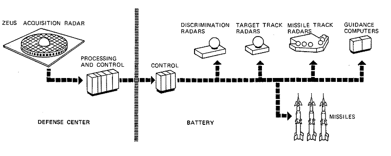
Figure 1-2. The NIKE-ZEUS Installation, Symbolic Block Diagram
The NIKE- ZEUS System was designed to provide a flexible, high-level defense against the complete spectrum of contemporary ballistic missile threats, and to be deployed to defend prime areas.1-3 The defense at each area was to be completely self-contained and able to function without external data or control. This capability, together with a modular-type design, allowed the defense to be tailored in accordance with the importance of the defended area. The ZEUS concept also permitted an orderly system growth that could take into account changes in the offensive or defensive situation. While the NIKE-ZEUS System was capable of independent operation, there were provisions for the North American Air Defense Command (NORAD) to exercise overall control and for ZEUS to transmit battle summary information to NORAD during an attack. In addition, ZEUS was designed to receive early warning data from the Ballistic Missile Early Warning System (BMEWS) and other sources.
Radar tracking data and command guidance were used to direct a high-performance defensive missile with sufficient accuracy to intercept and destroy an incoming warhead. Various elements of the system were so balanced that targets could be intercepted successfully at altitudes up to 500,000 feet and at ground ranges out to 75 nautical miles (this represented a nominal range for targets of a particular size, specifically 0.1 square meter, traveling at ICBM speeds).
The NIKE-ZEUS System was never deployed tactically because, by 1963, the rapid evolution of the ballistic missile threat made it necessary to redirect development to the more advanced NIKE-X System. Rapid changes during the ZEUS development period led to divergence between the installed research and development (R&D) equipment and the tactical NIKE-ZEUS System envisioned at the end of that period. The NIKE-ZEUS System described here is this envisioned tactical system; much of the equipment discussed thus never existed in the form described. Most of the R&D models used as examples in the text and shown in illustrations, however, were sufficiently representative so that, allowing for known differences, their appearance affords a clear picture of the tactical system planned at that time.
The envisioned tactical system would have appeared as shown in Figure 1-1. The planned tactical ZEUS installation, as shown in Figure 1-2, consisted of a Defense Center and at least one Battery, both to be located within the defended area.
Defense Center
The NIKE-ZEUS Defense Center, that part of the system shown in the right-hand portion of Figure 1-1, provided tactical control and acquisition data for as many as five Batteries associated with it in the defense of a local area. Its mission was to supply multichannel track-coordinate data on ballistic targets or decoy formations, and to select and transmit the necessary data and commands to the appropriate Battery.
The ZEUS Acquisition Radar (ZAR) was the major element in the Defense Center. The ZAR was a highly accurate, three-dimensional radar with substantial range against small targets. It had separate transmitting and receiving systems, and was able to scan 100 million cubic miles of space per second.4
The signal processing equipment at the Defense Center received the ZAR output and used it to determine trajectories of detected objects. These trajectories were examined to decide whether the objects were threatening the defended area. Those judged to be a threat were automatically designated for engagement by appropriate Batteries.
Although each Defense Center could operate independently, there were provisions enabling neighboring centers to act in concert. This capability would have been particularly advantageous if two or more centers had been needed to defend an area. In such a case, communication channels would have been provided for coordinating weapon assignment functions so that, if necessary, any one Defense Center could assume control of all area Batteries.
Communications also would have been established between centers defending nearby areas so that the ZAR at one center could provide data for the Batteries at another should the ZAR at the latter site be put out of action.
Figure 1-1. The NIKE-ZEUS Installation, Artist's Conception

Figure
1-2. The NIKE-ZEUS Installation, Symbolic Block Diagram
Battery
The NIKE-ZEUS Battery, in the left-hand portion of Figure 1-1, comprised all the elements required for carrying out the engagement of an assigned target.5 Specifically, this included radars for tracking and discrimination, defensive missiles, and computers for all the calculations needed to accomplish a successful intercept.
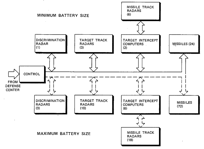
As indicated in Figure 1-3, the Battery was flexible, being composed of modular units so that it could be increased in size and capability when used to defend areas of greater importance. The number of missiles, radars, and computers for a given site could be tailored to a specific defense mission.
Each Battery had at least one Discrimination Radar (DR) able to track simultaneously individual objects within a specific grouping, or cloud of objects, and select the threatening ones for intercept. There also were Target Track Radars (TTRs) for highly precise, long-range tracking of small, high-speed objects to provide the data necessary for accurate terminal guidance of the defensive missile. Missile Track Radars (MTRs), also part of the Battery, were mounted on towers at the Battery Control Building (left center portion of the Battery in Figure 1-1). They tracked the defensive missiles and transmitted steering orders to them by means of a discrete multi-pulse code.4
In the Battery Control Building, defensive-missile steering orders were generated by the Target Intercept Computers (TICs) from target and missile position data supplied by the tracking radars. These orders directed each missile along an efficient trajectory toward the continually corrected predicted intercept and caused it to burst at the optimum point. Each computer was able to handle three separate target-missile combinations simultaneously.
The Battery also contained tactical control and monitoring equipment to provide automatic assignment of appropriate guidance equipment and missiles. In addition, there were displays to enable operators to monitor the automatic operations of the Battery with provision for manual intervention if required.
Figure
1-3. Minimum and Maximum Battery Sizes
As has been noted, the makeup of a particular Battery would depend upon its assignment. The practical minimum complement of equipment at a site was one Discrimination Radar (DR), three Target Track Radars (TTRs), two Target Intercept Computers (TICs), and six Missile Track Radars (MTRs). Twenty-four missiles were considered a normal complement for this minimum Battery.
Generally, the ratios of the number of different elements would not change as the Battery grew in size; however, the equipment's flexibility was such that this was not mandatory, and other Battery compositions could be tailored to the ever-changing threat. Figure 1-3 shows the effective maximum size of the NIKE-ZEUS Battery. Such a maximum did not represent an engineering limitation but rather a practical limit consistent with efficient operation. When a defense assignment required more equipment, additional Batteries could be used to achieve the desired level of defense.
The surveillance function for the NIKE-ZEUS System was to be performed by the ZEUS Acquisition Radar (ZAR) (Figure 1-4), a high-performance track-while-scan radar which could search for targets throughout a large volume of space. The ZAR's primary function was to detect any object — whether alone or accompanied by others in a cloud — that was approaching the particular defended area, and then to provide the data required for determining whether this object was threatening. The ZAR employed separate transmitting and receiving antennas which continually rotated in synchronism about vertical axes to provide full 360-degree azimuth coverages. The three vertical fan-beams generated by these antennas provided elevation coverage from 0 to 70 degrees. The structures had a rotational rate of 3-1/3 revolutions per minute so that the three beams provided new data on each object within the ZAR's essentially hemispherical coverage every 6 seconds. The characteristics of the ZAR are listed in Table 1-1.
Table 1-1
|
|
|
Transmitter (three per radar) |
|
|
Peak Power |
10 MW (*) |
|
Average power |
600 kW (*) |
|
Pulse rate |
97.7 pps |
|
Pulse duration |
650 μsec |
|
Duty factor |
0.06 |
|
Frequency |
|
|
Carrier |
Ten or fewer preselected frequencies between 870 and 960 MHz |
|
Frequency shift |
Carrier shifts on successive pulses among the preselected frequencies |
|
Chirp |
Instantaneous output frequency changes linearly 400 kHz during each pulse |
|
Transmitting Antenna |
|
|
Type |
Triangular three-pillbox array |
|
Gain |
28 dB |
|
Aperture |
80 ft by 2 ft, 6 in. (each of three) |
|
Beam width |
0.9° azimuth by 70° elevation |
|
Angular coverage |
Continuous in azimuth, 0° to 70° in elevation |
|
Diameter of fence |
660 ft |
|
Height of fence above pillbox aperture |
15 ft ± 6 in. |
|
Receiving Antenna |
|
|
Type |
Rotating hemispherical Luneberg lens with three receiver horn tower assemblies and stationary ground plane |
|
Gain |
41 dB |
|
Aperture |
80-ft diameter lens |
|
Beam width |
0.9° azimuth and elevation per feed cluster |
|
Number of beams |
Three sets of vertical beams spaced 120° with 77 beams in each vertical stack (**) |
|
Angular coverage |
Continuous in azimuth, 0° to 70° in elevation |
|
Ground plane |
600 ft in diameter |
|
Receiver |
|
|
Noise figure |
3. 5 dB (T = 720 °K) |
|
Number of receivers |
231 for 70° elevation coverage |
|
Collapsed pulse width |
4.5 μsec at 3 dB |
|
Angle determination |
Azimuth: pulse-count technique Elevation: beam splitting (comparison of adjacent receivers) |
|
Overall Characteristics |
|
|
Antenna rotation rate |
3-1/3 rpm |
|
Data interval |
6 sec |
|
Hits per beam pass |
Minimum of four (increases with elevation angle) |
|
Range performance |
600 nmi for 90% probability of generating a target report per scan (on a 0.1 sq m target) |
|
Range accuracy |
250 yd (1σ) |
|
Angular accuracy |
8 mils, elevation 4 mils, azimuth |
|
* - Waveguide loss between transmitter and antenna is less than 0.2 dB, therefore, essentially full power is radiated. ** - Based on an elevation coverage of 70°. |
|
Figure 1-4. R&D Model of ZEUS Acquisition Radar (Kwajalein)
Transmitting System
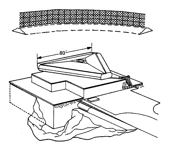
Each section of the transmitting antenna (Figure 1-5) had a pillbox configuration to achieve a vertical fan-beam of coverage. Three sections were arranged 120 degrees apart in azimuth on a common rotating structure to provide the high data rate. Each antenna section was fed by a separate transmitter, with a 600-kilowatt average power output, located in the building below the antenna.
The three transmitters could operate at different frequencies within the L-band. Each transmitter employed two wideband klystron tubes in parallel to obtain the required power. Chirp pulse techniques were used to collapse the long pulse employed for maximum range performance to a much shorter pulse for the required range resolution.
Figure
1-5. ZAR Transmitting System
Receiving System
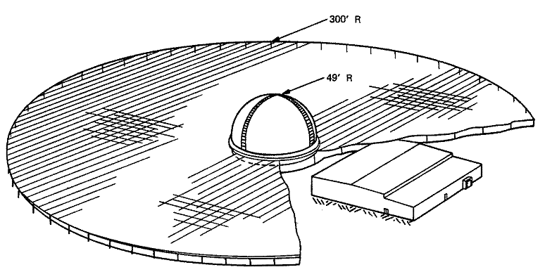
The receiving system (Figure 1-6) used a Luneberg lens with an associated reflecting ground plane. The solid, hemispherical lens was constructed of thousands of polyfoam blocks, containing tiny metal slivers, to obtain the necessary variation in dielectric constant through the lens media.6 The symmetry of the lens permitted the formation of beams in all directions, while its entire structure was used as an aperture. An array of vertically stacked receiving beams (Figure 1-7) permitted simultaneous coverage in elevation. Three of these arrays were spaced 120 degrees in azimuth. The feed horns and associated RF receiver equipment required for these arrays were embedded in the periphery of the lens. This, in turn, rotated in synchronism with the transmitting antenna. The remainder of the receiving equipment was located in the receiver building under the ground plane.
A simplified cutaway view of the lens media, horn trusses, ground plane, and drive mechanism is shown in Figure 1-8. The feed horns, each with its own complement of receiver front-end circuits, were mounted along each of the three horn trusses. Received signals, focused by the Luneberg lens and reflected by the ground plane, were picked up by one or more of the horns, depending upon the azimuth and elevation of the signal. The fan-type transmitting beam and the fan of receiving beams combined into a composite beam structure as illustrated in Figure 1-7.
Target position information was obtained for elevation using monopulse, and for azimuth using a pulse-count technique.
Figure
1-6. ZAR Receiving System
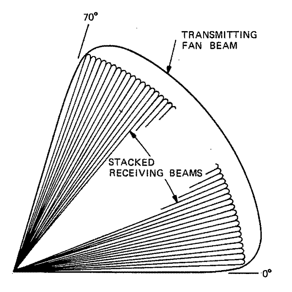
Figure
1-7. Multiple Receiving Beams Formed by Luneberg Lens
Signal Processing Equipment
Since it was anticipated that hundreds of objects — perhaps as in a massed decoy attack — would be within the ZAR's field of view, a special type of signal processing equipment was associated with the ZAR. This track-while-scan equipment not only had high-speed capabilities for processing many targets simultaneously, but also had special provisions for reducing its susceptibility to saturation. The primary functions of the ZAR signal processing equipment (Figure 1-9) were: (1) detection and consolidation of the radar returns, (2) initiation of tracks on new objects, (3) maintenance of tracks on each object by comparing new position with expected position based on previous data, and (4) prediction of impact point, the parameter used to determine which objects were threatening. All of these functions were performed completely automatically.7,8
The Target Data Consolidator used all the outputs from the individual receivers on the three horn trusses of the ZAR receiving antenna to detect targets and determine their positions. This was done by noting the truss and receiver at which a radar return was received, time at which the signal was received, and azimuth information (from a magnetic drum mounted below the Luneberg lens on the rotating portion of the antenna structure). Target elevation was derived by combining the signal-amplitude data from three adjacent receivers with stored data indicating the fixed elevation angle associated with each receiver. The range, azimuth, elevation, and time items were arranged into a "report" which comprised the output signal of the Target Data Consolidator.
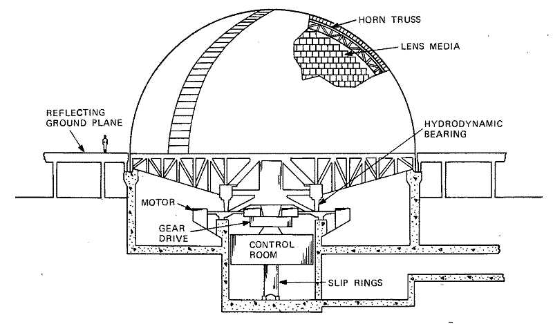
Figure
1-8. ZAR Receiving Antenna, Cutaway View

Figure
1-9. ZAR Signal Processing Equipment, Functional Block Diagram
The design of the NIKE-ZEUS System was such that when the Defense Center assigned a cloud of threatening objects to a Battery, a point within the cloud would be designated for use by a Discrimination Radar (DR) in tracking the entire cloud. The function of this radar was to provide sufficient information on all of the objects in the cloud so that non-lethal objects could be filtered out and true targets identified. The DR that was installed at Kwajalein is shown in Figure 1-10.
The DR was designed to cover clouds with diameters up to about 22 nautical miles. To maintain this coverage as the cloud approached, the antenna beamwidth was varied, according to range, from 2. 5 degrees at 500 nautical miles to 20 degrees at 60 nautical miles. This beamwidth variation was accomplished through use of a movable subreflector mounted in front of the main antenna reflector [see (A) of Figure 1-11]. The spacing between the subreflector and main reflector was varied to produce an adjustable degree of defocus, and thus width, of the beam. The characteristics of the transmitted beam are shown in (B) of Figure 1-11.
The DR transmitted long-duration, extremely high-power pulses because it had to track targets dispersed over a large area and begin its tracking at long ranges. To carry out the discrimination function, however, extremely high resolution of many objects was required. This was accomplished by compressing the long transmitted pulse in the receiver to provide fine range resolution and accuracy. Also designed into the DR was a system of multiple narrow tracking gates. These features made possible the separation of signal returns from the individual objects within the cloud for subsequent discrete analysis by data processing equipment associated with the DR.
The Discrimination Radar (with its signal processing equipment) had to be able to designate a target, which it had selected for engagement, to a TTR with sufficient accuracy for prompt and unambiguous transfer. To accomplish this, the DR generated three-dimensional position information on the objects it designated. A mono-pulse receiving system provided azimuth and elevation position signals for the object in the narrow range gate. These signals gave target position with respect to the beam axis. In addition, the transmitted pulses of the DR and the TTR were synchronized to facilitate target transfer. The return signals in both radars were collapsed to 0.25 microsecond to ensure that they would receive exactly the same signal from the selected object. These measures enabled transfer of an object from the DR to a TTR (when it was pointed in the general direction of the cloud) within 2 seconds.
The characteristics of the DR are listed in Table 1-2.
Table 1-2
|
|
|
Transmitter |
|
|
Peak Power |
40 MW (*) |
|
Average power |
78 kW (*) |
|
Pulse rate |
97.7 pps |
|
Pulse duration |
20 μsee |
|
Duty factor |
0.00195 |
|
Frequency |
|
|
Carrier |
1270 to 1400 MHz |
|
Diversity |
Random pulse-to-pulse shift among 13 preselected frequencies over entire band |
|
Chirp |
Instantaneous output frequency varies linearly over 10 -MHz range during pulse |
|
Antenna |
|
|
Type |
Cassegrainian |
|
Diameter |
22 ft |
|
Beamwidth |
Variable from 2. 5° to 20° |
|
Gain |
Varies from 36 dB at 2.5° beamwidth to 18 dB at 20° beamwidth |
|
Angular coverage |
Continuous in azimuth and 190° (-5.° to +185°) in elevation |
|
Radome |
Rigid, 47 ft in diameter |
|
Receiver |
|
|
RF amplifier |
Maser |
|
Equivalent noise temperature (overall) |
120 °K |
|
Intermediate frequency |
30 MHz |
|
Collapsed pulse width |
0.25 μsec at 3-dB points |
|
Angle determination |
Monopulse |
|
Range Capability (**) |
|
|
At maximum beamwidth (20°) |
85 nmi at center beam 60 nmi at 3-dB points of beam (22-nmi diameter cloud coverage) |
|
At minimum beamwidth (2.5°) |
700 nmi at center beam 500 nmi at 3-dB points of beam (22-nmi diameter cloud coverage) |
|
Target Position Accuracy (***) |
|
|
Range |
5 yd |
|
Angular |
10% of off-axis angle (0.4 mil minimum) |
|
* At the two output klystrons; losses in the guide, etc., are approximately 2.0 dB. ** With 0. 1 sq m target. *** 6 dB S/N (at half-power points of beam). |
|
Figure 1-10. R&D Model of Discrimination Radar (Kwajalein)
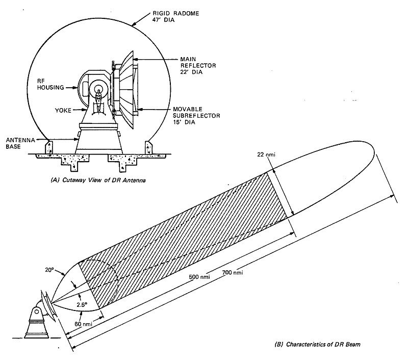
Figure
1-11. Discrimination Radar
Transmitter
The DR transmitter generated chirp pulses of high peak power. This power output was delivered from two special high-powered klystrons in the final RF amplifier.9 Transmitter operation was within the L-band with the output signal generated in 13 preselected frequency channels over the entire operating range. It was planned that, in tactical operation, these channels would be used randomly, on a pulse-to-pulse basis, to provide frequency diversity. Each channel was crystal-controlled for frequency stability.10
Antenna
The DR antenna [see (A) of Figure 1-11] was a parabolic reflector-subreflector structure employing a multimode monopulse feed and supported on a two-axis mount. The main reflector was a metallic paraboloid with an added overlay of metal wires which acted as a polarization twister. The subreflector was a non-metallic hyperboloid, embedded with horizontal metal wires, capable of being moved continuously for 18 inches with respect to the main reflector. This motion defocused the beam and caused the beam width to change. The design of the focusing/defocusing system is illustrated in Figure 1-12.
To obtain a narrow beam (2.5 degrees) for tracking at long ranges, the subreflector was positioned at the point where the image of the feed was at the focal point of the main reflector. In this condition, the rays were made nearly parallel by the main reflector and produced a narrow beam. Then, as target range decreased and the subreflector was moved in toward the main reflector, the image of the feed moved away from the focal point of the main reflector, causing the antenna to be defocused. When this occurred, the rays from the main reflector were divergent, and the beam was widened (up to a total width of 20 degrees).
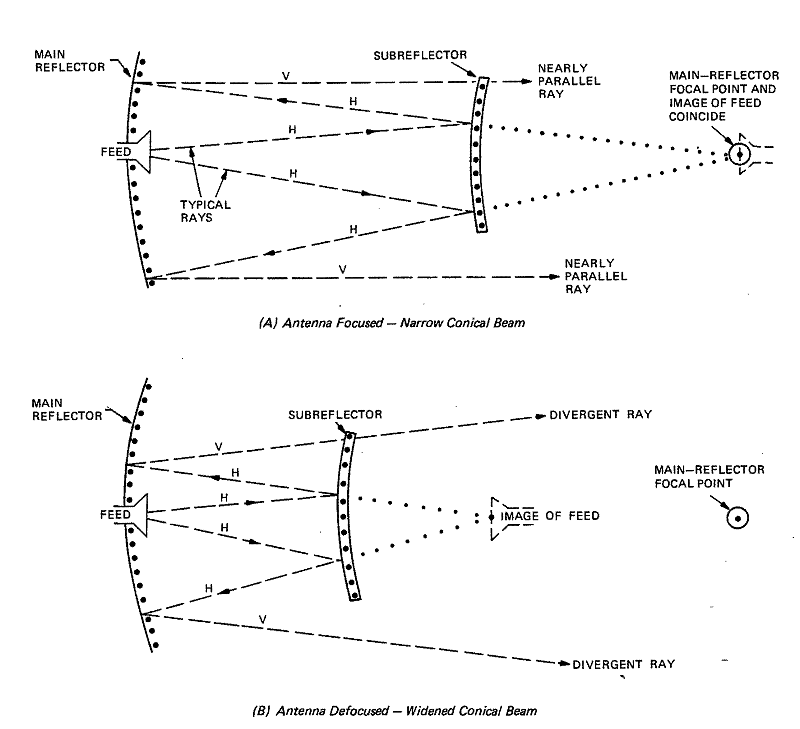
Figure
1-12. Focusing/Defocusing System of DR Antenna
Receiver
The DR used an extremely sensitive receiver to provide highly accurate position information on small objects in the target-decoy cloud. Maser RF amplifiers, operating at 2. 5 degrees Kelvin, achieved a very low noise level. The receiver's monopulsa design enabled it to provide simultaneous off-axis angle information on many objects,11 and its chirp circuits compressed (dechirped) the long transmitted pulse to 0.25 microsecond to provide satisfactory range resolution.
Data Processing Equipment
A major portion of the data processing equipment of the NIKE-ZEUS System was associated with the Discrimination Radar. The function of this equipment was to analyze tracked objects and perform tests on them to determine which targets were threatening. These targets then were arranged in a list according to their "likelihood" of being warheads. The DR data processing equipment comprised the All-Target Processor and the Discrimination and Control Computer. (See the section on Data Processing Equipment later in this chapter. )
The Target Track Radar (TTR), shown in Figure 1-13, was a precise, long-range, narrow-beam tracking radar which gathered highly accurate, continuous position data on very small, high-speed targets during the terminal phase of an engagement.12 A supercooled, super-low-noise, solid-state maser RF amplifier was used in conjunction with a high-gain Cassegrainian antenna to receive and amplify signal returns as low as 110 dB below 1 milliwatt.
The tactical TTR did not have a computer of its own, but was being designed to operate in conjunction with the Target Intercept Computer (TIC). However, because of testing requirements, each of the R&D models of the TTR had its own computing equipment which accomplished some of the functions that in a tactical deployment would have been done by the data processing equipment associated with the Discrimination Radar. In the tactical environment, the TTR would have made no decisions about targets, but would have been assigned a specific target (one at a time) by the TIC, based on the information that computer received from the Discrimination and Control Computer. Characteristics of the TTR are listed in Table 1-3.
Table 1-3
|
|
|
Transmitter |
|
|
Peak power |
10 MW (*) |
|
Average power |
5 kW (*) |
|
Pulse rate |
97.7 pps |
|
Pulse duration |
5 μsec |
|
Duty factor |
0.0005 |
|
Frequency |
|
|
Carrier |
5500 ± 250 MHz |
|
Diversity |
Random discrete changes among 50 frequencies in 500-MHz range |
|
Chirp |
Instantaneous output frequency varies linearly over 10 -MHz range during pulse |
|
Antenna |
|
|
Type |
Cassegrainian |
|
Diameter |
22 ft |
|
Beamwidth |
0.6° |
|
Gain |
48.5 dB |
|
Angular coverage |
Continuous in azimuth, 190° (-5° to +185°) in elevation, and ±25" about a zero reference in traverse |
|
Radome |
Rigid, 47 ft in diameter |
|
Receiver |
|
|
RF amplifier |
Maser followed by Traveling Wave Tube |
|
Intermediate frequencies |
First IF: 1280 MHz Second IF: 30 MHz |
|
Collapsed pulse width |
0.25 μsec at 3 -dB points |
|
Angle Determination |
Monopulse |
|
Equivalent Noise Temperatures at Antenna |
|
|
Antenna |
40°K |
|
Duplexer and waveguide |
99°K |
|
Maser amplifier |
13°K |
|
Circuit following mas er |
45°K |
|
Total radar system |
197 °K |
|
Range Capability — 6 dB S/N (**) |
|
|
Target
cross section |
580 nmi |
|
Target
cross section |
325 nmi |
|
Tracking Accuracy — 18 dB S/N (***) |
|
|
Angular (overall) |
0.18 mil |
|
Tracking jitter |
0.10 mil |
|
Boresight |
0.10 mil |
|
Mechanical error |
0.10 mil |
|
Data takeoff |
0.05 mil |
|
Range |
2 yd |
|
Range |
2 yd |
|
*
At the two output klystrons; losses in the guide, etc., are
approximately 2.7 dB. |
|
Transmitter
The TTR transmitter provided a narrow chirp pulse with 10 megawatts peak power. The transmitter consisted of a chirp generator and synchronizer, a low-level section, and a high-level section.13
A stabilized local oscillator in the low-level section generated a signal at the transmitter carrier frequency from low-frequency crystal oscillators. This local-oscillator signal was mixed with a chirped signal for good range resolution even though long, high-energy pulses were transmitted.
The high-level section of the transmitter provided final amplification of the pulses to be transmitted. This amplification was accomplished by two 5-megawatt klystrons whose outputs were combined. Figure 1-14 shows the klystron amplifier section, with the two output klystrons installed in their insulating-oil tanks.
Antenna
The TTR antenna (see Figure 1-13) was a 22-foot-diameter parabolic reflector-subreflector arrangement supported on a three-axis (elevation, traverse, azimuth) mount. A three-axis mount (instead of the more usual two-axis type) was chosen to allow the tracking of extremely high-speed ballistic missile targets directly overhead, where the required axial velocities and accelerations would be prohibitive for the two-axis type.14 Under these conditions, such targets could be tracked to altitudes as low as 50,000 feet; ballistic missiles not passing through the zenith could, of course, be tracked to lower altitudes.
The TTR antenna mount weighed about 150,000 pounds and was positioned by hydraulic motors operating in pairs on each axis. These hydraulic drives provided a maximum slew rate in azimuth and elevation of 1.25 radians per second, and in traverse of 0.5 radian per second.
Figure 1-13. R&D Model of Target Track Radar Antenna (Whippany)
Figure 1-14. TTR Klystron Amplifier Section
Figure
1-15. Comparison of Range Obtained with Maser Receiver and Other
Receivers
Receiver
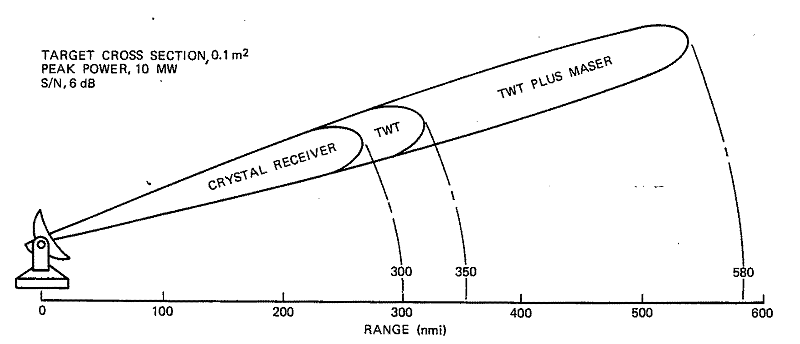
The TTR receiver used a super-low-noise, solid-state maser for the first RF amplifier, followed by a Traveling Wave Tube (TWT) for final amplification. The equivalent noise temperature of the RF amplifier, the most critical source of noise in the receiver, thereby was reduced enormously. In previous radar receivers, a receiver noise temperature of 3000 degrees Kelvin was not unusual. (Figure 1-15 compares graphically the performance of the maser receiver with other types of receivers.) The overall TTR system noise temperature was 197 degrees Kelvin.15
Data Processing Equipment
As previously stated, the tactical TTR was not to have any data processing equipment of its own. However, those R&D models built and operated during the test program were equipped with data processing equipment to meet the test objectives. Each such TTR was equipped with a Target Intercept Computer as well as with peripheral equipment to provide the necessary interface with the computer.
The Missile Track Radar (MTR) provided position data on the defensive missile to the Target Intercept Computer (TIC). It also transmitted steering, burst, and other orders from the TIC to the defensive missile via the radar beam. This radar could track the beacon-equipped ZEUS missile to a range of 75 nautical miles with an overall angular accuracy of 0.2 mil. A combination of different pulse codes and frequencies permitted a particular MTR to communicate with a defensive missile without interfering with other missile-radar combinations. As many as 450 missiles could be under control in a defense area without mutual interference. The characteristics of the MTR are listed in Table 1-4. The MTR antennas of a Battery were mounted on towers that were part of the Battery Control Building (Figure 1-16) which also housed the radar equipment and the Target Intercept Computers.
Table 1-4
|
|
|
Transmitter |
|
|
Peak power |
300 kW (*) |
|
Average power |
108 W (*) |
|
Pulse rate |
Normal: 162.8 groups per sec (9 pulses in each group) Burst: 488.4 groups per sec (4 pulses in each group) |
|
Pulse duration |
0.25 μsec |
|
Duty factor |
0.00036 |
|
Frequency |
8525 to 8925 MHz |
|
Antenna |
|
|
Type |
Cassegrainian |
|
Diameter |
4 ft |
|
Beamwidth |
2° |
|
Gain |
38 dB |
|
Angular coverage |
Continuous in azimuth and 203° (-11. 5° to +191.5°) in elevation |
|
Receiver |
|
|
Frequency |
8960 to 9600 MHz |
|
Noise figure |
9 dB |
|
Intermediate frequency |
25 MHz |
|
Angle determination |
Monopulse |
|
Tracking Accuracy — 26 dB S/N |
|
|
Angular
(per coordinate) |
0.10 mil (**) |
|
Angular
(per coordinate) |
0.10 mil (**) |
|
Angular
(per coordinate) |
0.10 mil (**) |
|
Angular
(per coordinate) |
0.05 mil (**) |
|
Angular (overall) |
0.18 mil |
|
Range |
2 yd (***) |
|
Range |
2 yd (***) |
|
*
At magnetron; losses in the guide, etc., are approximately 2
dB. |
|
Transmitter
The MTR transmitter provided a peak power output of 300 kilowatts. It consisted of a hardtube modulator driving a magnetron that was automatically tuned to any one of nine fixed frequencies spaced at 50-MHz intervals. The transmitter could be switched to any of these nine separate ZEUS missile receiver frequencies quickly and accurately. An automatic frequency control unit referenced the transmitter signal to the X-band harmonic outputs of a transistorized, crystal-controlled frequency standard.16
The MTR transmitter was installed below the antenna in the Battery Control Building, rather than in the rotating structure, to keep the size of the rotating portion of the antenna mount to a minimum. RF power was fed to the antenna via X-band waveguide and two rotary joints, one in the azimuth axis and the other in the elevation axis. The waveguide was pressurized to 35 pounds per square inch absolute to prevent breakdown and thus ensure full power output.
Antenna
A 4-foot-diameter Cassegrainian antenna (Figure 1-17), on a two-axis mount, provided a gain of 38 dB. The mount could rotate continuously in azimuth and track in elevation from 11.5 degrees below the horizon through the zenith to 11.5 degrees below the horizon on the opposite side. The slew rate in each axis was about 2 radians per second. Only 5 seconds was required from the end of an engagement for the radar to lock on to the next missile.
Figure 1-16. Battery Control Building with Missile Track Radar Antennas
Figure 1-17. R&D Model of MTR Antenna (Whippany)
Receiver
The MTR's monopulse receiver had a noise figure of 9 dB and a bandwidth of 10 MHz. It could be automatically tuned to any one of the nine fixed frequency channels used by ZEUS missile transmitters; these channels were spaced at 80-MHz intervals.
The signals from the missile transmitter, intercepted by the MTR antenna, were fed to a comparator which converted the horn inputs to azimuth, elevation, and sum signals. These in turn were fed to a converter assembly, where they were mixed with the local oscillator output to produce IF signals. The local oscillator was a klystron, the frequency of which was controlled to within ±3 MHz by an automatic frequency control system, thus locking the receiver to the signals from the missile.
The gains of the sum, azimuth, and elevation channels of the receiver always had to be kept equal to preserve interchannel balance, even though the received signals may have had amplitudes varying over a range of 94.5 dB. This automatic gain control was achieved through the use of transistorized digital-amplifier and attenuator-switching circuits, which could adjust gain in 1.5-dB steps. The range unit in the receiver also employed transistorized circuits and digital techniques in furnishing data to the Target Intercept Computer. Azimuth and elevation angle data were derived from precison resolvers on the two antenna axes and were encoded for transmission to the computer.
The NIKE-ZEUS missile (Figure 1-18) had three major sections — the booster or first stage, the sustainer or second stage (also called the mainstage), and the nose section or jethead.17 To avoid additional complexity, the same missile-borne guidance and control equipment was used to position the missile's control surfaces both inside and outside of the atmosphere. Within the atmosphere, roll control and steering were accomplished by aerodynamic forces acting on four control fins. Outside the atmosphere, reaction control was used, with the gases expelled through jet nozzles in the same control surfaces. Figure 1-19 shows the NIKE-ZEUS missile ready to launch. Missile characteristics are given in Table 1-5.
Table 1-5
|
|
|
Overall |
|
|
Length (including booster) |
50 ft, 2 in |
|
Gross Weight |
24,200 1b |
|
Payload |
468 lb |
|
Booster |
|
|
Length |
17 ft, 6 in |
|
Diameter |
34 in |
|
Gross weight |
12,900 lb |
|
Solid propellant |
Polybutadiene acrylic acid (PBAA) |
|
Sustainer |
|
|
Length |
15 ft, 2 in |
|
Diameter |
36 in |
|
Gross weight |
8, 250 lb |
|
Solid propellant |
PBAA |
|
Ablative covering |
Phenolic nylon skin |
|
Maximum skin temperature |
600° F |
|
Maximum operating altitude |
84,570 ft |
|
Jethead |
|
|
Length (including probe) |
17 ft, 6 in |
|
Diameter (maximum) |
36 in |
|
Gross weight |
3050 lb |
|
Solid propellant (jethead motor) |
PBAA |
|
Ablative covering |
Phenolic nylon skin |
|
Steering and roll control: |
|
|
Within atmosphere |
4 control fins |
|
Outside atmosphere |
Motor exhausting through fin nozzles |
|
Warhead section |
|
|
Tactical missile |
Warhead and arming |
|
R&D missile |
Telemetry |
Figure 1-18. NIKE-ZEUS Missile, Cutaway View
Figure 1-19. NIKE-ZEUS Missile in Launch Pit
Figure 1-20. ZEUS Missile-Borne Guidance Unit
The missile-borne guidance unit, shown in Figure 1-20, received and decoded the steering orders and certain commands, such as arm and burst, relayed to it by the MTR.18 These coded instructions were received as groups of pulses modulating a carrier whose frequency was in the range from 8525 to 8925 MHz. The guidance unit comprised a transmitter, a receiver, a decoder, a stable platform, part of the missile's autopilot, and several on/off circuits. There were four identical antennas spaced at 90-degree intervals on the outer housing of the guidance unit and enclosed in strakes (see Figures 1-18 and 1-19). Each antenna was a cylindrical waveguide terminated in a diverging lens to give hemispherical coverage. Two of the antennas were used for transmitting and all four were used for receiving.
To prevent interference among the MTR-missile combinations in a Battery, a different combination of carrier frequency and pulse code was used for each missile. The missile's receiver had a dual Traveling Wave Tube RF amplifier and a dual crystal detector, each channel being used for the signals from two of the missile's antennas.
Functional Organization
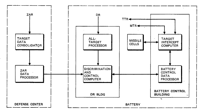
Data processing equipment in the NIKE-ZEUS System was concerned with processing position information from the radars, planning and controlling system operations (tactical control), and accomplishing target selection and decoy discrimination. These functions were implemented by six major computing equipments, as illustrated in Figure 1-21, plus associated peripheral equipment.19
The Target Data Consolidator detected targets and determined their positions.20 The ZAR Data Processor evaluated the threat and provided data on threatening objects to the Batteries, where appropriate Battery elements would be assigned to engage each target. This target information also was to be used by the Batteries to determine (1) when to fire defensive missiles and (2) what command-guidance orders should be given during the early stages of missile flight. The ZAR Data Processor was to have a capacity of several hundred tracks depending upon the size of the NIKE-ZEUS installation.
The All-Target Processor was a special-purpose digital computer which could process data on as many as 625 objects in a target-decoy cloud. These data were received from the Discrimination Radar in analog (video) form and were encoded into digital form by the processor. The All-Target Processor then used the slowdown, scintillation, and cross-section characteristics of the objects to eliminate obvious decoys. Data on the remaining objects were passed to the Discrimination and Control Computer, where additional and more rigorous discrimination tests were performed.
The Discrimination and Control Computer could accept data on as many as 50 targets from the All-Target Processor. This computer also used the slowdown, scintillation, and cross-section characteristics of the objects to eliminate those that had the characteristics of decoys. The computer then generated a composite likelihood ratio for each remaining object.21 The likelihood ratios, along with acceleration, velocity, and position data on all the remaining objects, were sent to the Battery Control Data Processor where the final determination for engagement was made.
Figure
1-21. Major Computing Equipments of NIKE-ZEUS, Simplified Block
Diagram
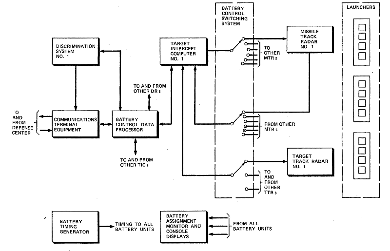
Signal flow at the Battery is shown on Figure 1-22. Selections of Missile Track Radars and Target Track Radars for a given engagement were made by the Battery Control Switching System, at the direction of the Target Intercept Computer. The timing for all Battery units was provided by the Battery Timing Generator and communication with the Defense Center was via the Communications Terminal. The Battery Assignment Monitor and Console Displays provided the required man/machine interface.
The Battery Control Data Processor was designed to perform the tactical control operations required by the Battery primarily in an engagement involving decoys. Its functions were to include engagement planning (that is, how many missiles to launch, on what trajec-tories, and at what time) and engagement execution (that is, which object or objects to intercept). This equipment received position and target-likelihood data from the Discrimination and Control Computer and provided target-designation, engagement, and equipment-request signals to the Target Intercept Computers.
The Target Intercept Computer made all the computations required to determine the guidance orders enabling the defensive missile to intercept a hostile target. Each Target Intercept Computer handled the computations required for six separate concurrent engagements by time-multiplexing in one circuit path. The computing cycle was divided into six equal periods, each handling all computations for an engagement. The Target Intercept Computer utilized Missile Track Radar information on the position of the ZEUS missile; it also received target position information from the ZEUS Acquisition Radar, the Discrimination Radar, or the Target Track Radar. From this information, it computed and generated coded acceleration orders for the Missile Track Radar to transmit to the defensive missile. During a normal interception, it generated a "jet ignite" command to start the jethead motor and a "burst" command when the ZEUS missile reached the point on its trajectory which produced the maximum kill probability. Besides generating guidance orders, the Target Intercept Computer's functions included ( 1) performing certain computations needed by the Target Track Radar and (2) furnishing engagement data and status information to the Battery Control Data Processor. Figure 1-23 shows the Target Intercept Computer; its characteristics are given in Table 1-6.
Table 1-6
|
|
|
Type of logic |
Resistance-coupled transistor logic |
|
Type of arithmetic |
Two's complement |
|
Type of operation |
Parallel |
|
Word length |
25 bits including sign and parity |
|
Number representation |
Fractional |
|
Instruction repertoire |
54 instructions |
|
Modes of operation |
Assigned, ready, and off-line |
|
Arithmetic Unit |
|
|
A- register |
24-bit double rank |
|
Q-register |
24-bit double rank |
|
N-register |
24-bit single rank |
|
Speed of operation |
|
|
Addition and subtraction |
2.5 μsec |
|
Multiplication |
7.5 μsec |
|
Division |
15.0 μsec |
|
Square root |
27.5 μsec |
Storage |
|
|
Permanent memory |
|
|
Capacity |
24,576 25-bit words |
|
Type of read-out |
Nondestruct |
|
Cycle time |
2. 5 μsec |
|
Variable memory |
|
|
Capacity |
4,096 25-bit words |
|
Type of read-out |
Destruct |
|
Cycle time |
2.5 μsec |
|
Reference memory |
|
|
Capacity |
15 16-bit words |
|
Type of read-out |
Destruct |
|
Cycle time |
1.25 μsec |
Modular Structure
In the NIKE-ZEUS System (as in the successor systems) it was planned that the data processing equipment be completely modular. The equipment was constructed of a hierarchy of "building blocks, " used in the numbers and combinations required to accomplish specific functions.
The largest building block was the NIKE-ZEUS High-Speed Digital Computer (Figure 1-24). Each of the major computing equipments shown in Figure 1-21 used at least one of these computers. Next below the level of the digital computer was the D-unit (Figure 1-25), the unit of replacement for field maintenance. D-units were slide-mounted in special racks. Each D-unit was composed of flat, chassis-like assemblies called C-planes (Figure 1-26). C-planes were stacked vertically (up to a maximum of six) to form a D-unit.
The lowest-unit building blocks were the A-and B-modules. The basic A-module (Figure 1-27) contained four transistor inverters, which could be connected externally to form double inverters, flip-flops, and other logic elements. A-modules were arranged in an array seven modules wide by ten modules long on the C-plane. Special packages, in multiples of the A-module size, were referred to as B-modules.
Figure
1-22. Signal Flow at Battery, Simplified Block Diagram
Figure 1-23. Target Intercept Computer
Figure 1-24. NIKE-ZEUS High-Speed Digital Computer
Figure 1-25. D-Unit for NIKE-ZEUS Computer
Figure 1-26. C-Plane for NIKE-ZEUS Computer
Figure 1-27. Logic A-Module for NIKE-ZEUS Computer
In addition to the standard A-module inverters, some 35 special-purpose circuits were required. Among these circuits, which took up only about 10 percent of the equipment, were sense amplifiers, inhibit generators, current generators, relay drivers, delays, and dummy loads. Wherever possible, these circuits were built into the basic A-module package.
Another important feature of the modular units making up the NIKE-ZEUS data processing equipment was the diffused-base germanium transistor (designated 2N559) used in the logic circuits. This device was developed for NIKE-ZEUS by Bell Laboratories and produced in large numbers by the Western Electric Company. Major emphasis was placed on providing the high degree of reliability needed by the system; a demonstrated reliability of only eight failures in 109 hours was achieved.
Stores
Three independent data processing stores were included in the NIKE-ZEUS System:
(1) a permanent memory called a program store;
(2) a variable memory called operand store; and
(3) a reference memory called reference control store. Characteristics of these stores are given in Table 1-6.
The program store consisted of twistor wires and program cards containing a pattern of small vicalloy magnets.22 As shown in Figure 1-28, a twistor is made up basically of a conductor around which is helically wrapped a strip of magnetic material. (The picture shows a greatly enlarged model of a twistor wire. ) This material has a square-loop B-H characteristic, and the application of a magnetic field to a twistor element switches it from one magnetic state to another. Such a change of magnetic state induces readout current in the conductor. If a relatively strong external magnetic field is maintained on the twistor element, this element becomes magnetically saturated and readout results in a "zero. " Stored programs or constants can be set up in an array of twistors; a "zero" readout is obtained by placing a permanent magnet near each twistor element, and a "one" is obtained without the magnet. A 48-word variation of the program store was called the twistor input switch. Storage slots in this equipment were similar to those in the program store, but the permanent magnets were replaced by direct-current solenoids.
Figure 1-28. Twistor Wire
The twistor type of memory (see Figure 1-29) was developed by Bell Laboratories specifically for NIKE-ZEUS computers. It has the advantages of (1) high operating speed, (2) readily changeable programs, and (3) the capability of a high rate of manufacture at low cost. A system of automatic memory-card production was devised; the program was prepared in symbolic form and the program cards were produced by a special machine. Twistor arrays also were used for switching in the NIKE-ZEUS System.
Figure 1-29. Twistor Store
The operand store was used to store data temporarily during calculations. Ferrite cores were used for the storage elements and the store information was changed electronically on command. The reference control store was used for input-output control and as a link register for storing return addresses and subroutine jumps. It also used the words it had in storage to modify the addresses of other words being operated on in the computer. (This step was required in many programs in which the address of the next operation was based on the results of the previous operation.) A high-speed, ferrite-core, word-organized store was developed for this reference memory.