Fig. 1 Typical Mars Convoy in Earth Orbit
|
SOURCE Proceedings of the American Astronautical
Society VOLUME 15 |
[Program Director-NOVA , General Dynamics/Astronautics]
|
The NOVA design studies currently being conducted under the direction of the Marshall Space Flight Center are aimed at defining the most desirable launch vehicle for the heavy space missions of the 1970's. To help make these missions technically and economically feasible, NOVA must achieve a big step forward in payload capability and in cost effectiveness. The task of assembling manned Mars expeditions in Earth orbit weighing several thousand tons favors launch vehicles in the million pound payload class. Significant cost reductions can be achieved by recovery and re-use of high cost components or of complete stages. Representative NOVA configurations developed by General Dynamics/Astronautics and Martin/Baltimore , the NOVA Study contractors, are described. |
The NOVA launch vehicle has been defined as the next larger launch vehicle after Saturn V. One of the main objectives of the NOVA System is the support of manned planetary expeditions and, most particularly, of the exploration of Mars. There is a wide range of possible configurations to be considered for NOVA, depending on when NOVA is required and what level of technological advancement is to be incorporated in its development. To help define the best Nova System, Marshall Space Flight Center has contracted with the Astronautics Division of General Dynamics Corporation in San Diego and with the Space Systems Division of Martin-Marietta Corporation in Baltimore for two parallel design studies. The NOVA designs developed by the contractors up to this time are described here.
The complete spectrum of missions for NOVA includes, in addition to the launching and support of manned interplanetary expeditions: the support of large scale lunar base operations with cargo and personnel transport to the lunar surface; the support of Earth orbital operations, including the launching of heavy space stations into difficult orbits and the launching of maneuverable spacecraft; and possibly the launching of high velocity unmanned probes for the exploration of the far reaches of the solar system. To help make these missions technically and economically feasible, NOVA must achieve a big step forward in payload capability and in cost effectiveness. The next step in payload capability beyond Saturn V brings us into the million pound orbital payload class. Good cost effectiveness, i.e. , a low cost in dollars per pound of payload delivered to orbit, is a complex matter involving payload capability, performance, reliability, development and production cost, launch rate and operational life, and requires special provisions such as partial or complete recovery and re-use of the launch vehicles. A report on the cost effectiveness analysis and trade-offs being performed under the NOVA studies is beyond the scope of this paper. It is important, however, to keep the cost criterion in mind when reviewing the proposed NOVA configurations. The achievement of low cost space operations is essential in making any ambitious space exploration programs economically feasible and acceptable to the Nation.
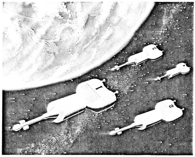
Turning now to the specific requirements of the manned Mars expedition, we must first make a working assumption regarding the make-up and characteristics of the Mars spacecraft. A typical Mars convoy, based on concepts developed under the EMPIRE studies (Ref. 1), is shown in Fig. 1.
Fig. 1 Typical Mars Convoy in Earth Orbit
The convoy is composed of four spacecraft which are assembled in Earth orbit prior to departure towards Mars. Two of the spacecraft may be manned and the other two unmanned, carrying service supplies and equipment. The aft end of the spacecraft is the Earth Escape Stage, consisting of the propellant tanks and engines required to inject the spacecraft into the Mars transfer trajectory. Amidships, protected by a thermal and meteorite shield, are the propulsion systems required for maneuvers in subsequent stages of the mission. The crew and equipment compartments are towards the forward end. Each spacecraft, including its Earth Escape Stage, may weigh on the order of 1.5 to 2 million pounds. Because of the weight and the shape of the spacecraft, it is expected that they will be assembled in Earth orbit from smaller "launch modules." These launch modules are not necessarily identical to the "mission modules" into which the spacecraft may be subdivided to accommodate the various stages of the Mars mission; a launch module may include several mission modules.
For example, the Earth Escape Stage and the forward part of the spacecraft could be launched separately, then connected together in orbit. A NOVA vehicle with a million pound payload capability would allow the assembly of each spacecraft from two launch modules, thus requiring--as a minimum-- two successful NOVA launches per spacecraft. A NOVA capable of delivering 700,000 lb to Earth orbit would entail at least three launches per spacecraft, taking into account the fact that the launch modules will not be exactly of equal weight. Even more launches would be required with further decreases in NOVA payload capability. The time span used for assembling the convoy in Earth orbit should be kept as short as possible, to minimize the problems connected with propellant boil-off, reliability degradation, and orbital decay. A maximum of 6 months has been postulated for this operation. Although this might seem like a long time, it results in NOVA launch rates that are extremely high as judged by our present standards.
The above description serves only to provide a tangible example and a reasonable working assumption for the NOVA vehicle studies. The actual characteristics of a Mars convoy are, of course, not really known at this time.
We can now address ourselves to the requirements that are imposed on the launch vehicle by the task of assembling a Mars expedition in Earth orbit. First, the launch vehicle must allow a reasonable degree of freedom in the selection of the assembly orbit, without compromising the efficiency of the launch operations. Parameters which are involved in the selection of the assembly orbit altitude are shown in Fig. 2.
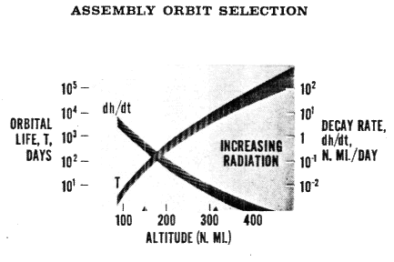
Fig. 2 Assembly Orbit Selection Parameters
The orbital life time and the altitude decay rate are plotted against altitude, for a range of weight/drag ratios (W/CDA) typical of Mars spacecraft modules. From the viewpoint of energy requirements in the launch vehicle, it is desirable to select the lowest possible altitude. However, if the assembly and check-out of the Mars convoy is to involve time spans of several months, altitudes of 200 nautical miles or more are required for adequate orbital lifetimes. Where extensive rendezvous operations are contemplated, there is also some advantage in selecting orbits with periods that are an integer fraction of 24 hours, so that the orbital plane and the spacecraft pass over the launch site together once every day. Altitudes corresponding to 16 and 15 orbits per 24 hours are shown by tick-marks on the altitude scale. The 15 periods/day orbit, at an altitude of 307 n mi (569 km), is probably the highest assembly orbit that need be considered. Above this altitude the radiation environment due to both natural and man-made radiation belts becomes an increasing problem for long term manned operations. Consequently, the 307 n mi orbit has been used as the standard assembly orbit in the NOVA studies.
A typical NOVA launch trajectory is shown schematically in Fig. 3.
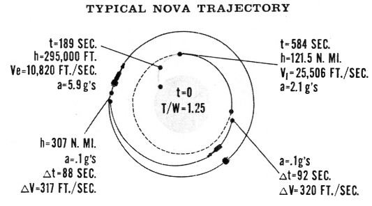
Fig. 3 Typical NOVA Trajectory (not to scale)
A two-stage liquid propellant vehicle has been selected for this example. The vehicle lifts off vertically, at a thrust to weight ratio of 1.25, then pitches over into a gravity turn. Maximum acceleration occurs at first stage burn-out. The second stage then places the vehicle into a 121 n mi (225 km) circular parking orbit. After an appropriate coast period, transfer to the 307 n mi assembly orbit is initiated along a Hohmann ellipse. This procedure has two major advantages. Although it is possible to inject the payload directly into the higher orbit, this requires more energy per pound of payload and results in a lower payload for a given vehicle (Table 1).
|
Table 1 ORBITAL PAYLOAD COMPARISON |
||
|
Orbit Altitude , n mi |
Mode |
Payload, lbs |
|
121 |
Direct |
1,130,000 |
|
307 |
Hohmann |
1,000,000 |
|
307 |
Direct |
820,000 |
Even more important, direct injection requires extremely precise timing of the launching if the ascending vehicle is to be placed into close proximity with a rendezvous target that is already in orbit. It also requires the target to be at a prescribed position in its orbit at the instant when the target's orbital plane passes over the launch site. By first placing the ascending vehicle into a parking orbit (which has a shorter period than the assembly orbit) it is possible to coast in the parking orbit until the two objects are in the correct relative position for initiating the Hohmann transfer. In addition, the transfer mode affords a better opportunity for making orbital plane changes. This further opens the launch window, since it is no longer necessary to launch at the precise time when the orbital plane of the target passes over the launch site.
The velocity increments required at the perigee and apogee of the Hohmann ellipse can be provided by restarting the second stage of the launch vehicle. The NOVA design studies indicate, however, that it is more advantageous to provide a small separate transfer stage, or "transtage." This transtage can also be utilized for the final rendezvous and docking maneuvers. When NOVA is used for placing payloads directly into Earth escape trajectories, a third stage (which may be chemical or nuclear) is used in place of the transtage. The common denominator for all missions is the 121 n mi (225 km) parking orbit and payload capabilities are referenced to this orbit. Table 1 provides a comparison of the payloads that can be delivered by the same million pound class vehicle to the 121 n mi and 307 n mi orbits.
The payload capability of the launch vehicle used in any large scale orbital assembly program has a profound effect on the launch facility requirements in addition to its obvious effect on the complexity of the orbital assembly operations. This point is illustrated in Fig. 4, for the assembly of a 4-spacecraft convoy from varying numbers of launch modules.
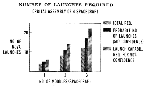
Fig. 4 Number of NOVA Launches Required
If the launch vehicle is large enough to lift a complete spacecraft in a single launch (1 module per spacecraft), then 4 launches would be required in the ideal case (no failures). If we assume a launch vehicle reliability of 80 - 90%, and also make allowances for the possibility that one or more of the spacecraft may not check out satisfactorily in orbit and may require replacement, we find that, on the average, 5 launches will be required. This means, however, that in about half the cases more than 5 launches will be needed. If we are equipped to make only 5 launches during the time period allotted to the orbital assembly operation, we may expect to have all 4 spacecraft ready for departure from Earth orbit at the prescribed time in only one out of every |two attempted missions. We may call this the 50% confidence level. Since Mars windows occur only once every two years and considerable expense and prestige are associated with assembling an expedition of this sort, we may want to insure a much better chance of success, say 90%. To accomplish this, we must be equipped to make 6 launches in the prescribed time period, although the actual number of launches would still average out at 5 over several missions.
If the launch vehicle is sized so that 2 payloads are needed for each spacecraft, then 8 launches would be required in the ideal case. Additional factors now come into play, namely, the reliability of the rendezvous and docking operation, and the possibility of spacecraft damage during docking. Based on some tentative reliability assumptions for these operations, the probable number of launches is 11, and the launch capability required for 90% confidence is 14. If a still smaller launch vehicle is used, requiring 3 payloads per spacecraft, then the number of launches for the three cases considered above increases to 12, 17, and 22, respectively. These launchings must be accomplished within a period of six months or less, imposing a severe strain on the launch facilities and operations. [*]
[* – See "Launch Facility Requirements for Mars/NOVA Vehicle," by Howard Keyser, which is the next paper in this volume.]
The larger launch vehicles minimize orbital assembly problems, reduce orbital assembly time, and decrease launch facility complications and costs. The lowest number of launches would be achieved, of course, if the launch vehicle were made large enough to carry the complete spacecraft as a single payload. As stated previously, each spacecraft may be expected to weigh 1.5 - 2.0 million pounds. It is possible to design a NOVA vehicle with this payload lifting capability. Present indications are that such a design would stretch the limits of practicability: number of engines required (or engine size), transportation and handling problems, and acoustical environments are some of the limiting factors. Another decisive consideration is that of payload shape. Optimum spacecraft arrangements tend to be long and loosely packed. This leads to large, awkward payload fairings and very low payload densities when the spacecraft is installed atop the launch vehicle. Severe problems in the areas of vehicle stability, structural dynamics, launch facility height, etc. , would be encountered in attempting to launch a fully assembled spacecraft. Major attention in the NOVA design studies has, therefore, been centered on vehicles with payload capabilities around one million pounds, corresponding to two payloads per spacecraft, although smaller vehicles have also been studied.
The vehicles being examined in the NOVA studies cover a wide range of technological development, from state-of-the-art designs to very advanced concepts, with a correspondingly wide range in the time spans required to bring these vehicles to the point of operational availability. The vehicles presented here can be conveniently categorized in three classes.
Class I might be termed the state-of-the-art NOVA. The designs are based on well established technology and propulsion systems are based on current development or demonstration programs (F-1 and M-1 engines, 260 - 325 in. solid propellant motors). Performance, costs, and schedules can be predicted with reasonable confidence. These vehicles could become available for operational use in the early to mid-1970's.
Class II might be termed the advanced NOVA. These designs are based on technological advancements that may reasonably be expected to occur in the near future and that can be programmed with some degree of realism. High chamber pressure engines and altitude compensating systems are included in this class. Operational availability falls in the mid or latter 1970's.
Class III might be termed the unconventional NOVA. These concepts are based on far-reaching advancements in technology, which may or may not materialize. Advanced rocket and air augmentation systems are included in this class. Operational availability is quite uncertain; it may occur in the late 1970's or early 1980's.
The Class I and Class II vehicles presented here are the result of an extensive process of evaluation and selection from a much larger number of possible configurations. The Class III vehicles, on the other hand, are in an early conceptual stage of their evolution.
The NOVA studies indicate that within Class I the choice soon narrows down to vehicles using either F-1 engines in the first stage and M-1 engines in the second stage, or large solid motors in the first stage and M-1 engines in the second stage.
Figure 5 shows the Martin Company versions of these Class I vehicles. [*]
[* – Some of the configurations developed by Martin and by General Dynamics/Astronautics are quite similar. In these cases, only one configuration is described and only the significant differences in the other company's approach are noted.]
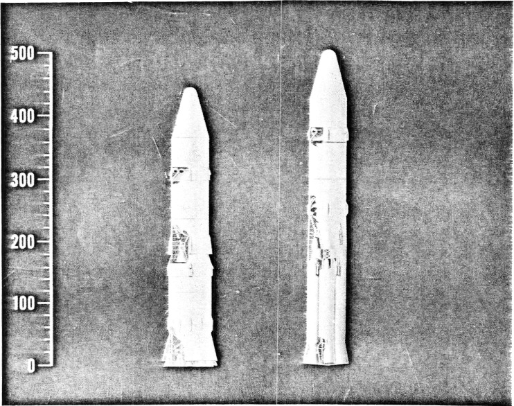
Fig. 5 Martin Class I Configurations
The vehicle on the left is the liquid propellant design, using LO2/RP-l in the first stage and LO2/LH2 in the second stage. First stage propulsion is provided by 18 advanced F-1 engines. These engines are uprated versions of the F-1 engines being developed by Rocketdyne for the Saturn V, and are rated at 1,800,000 lb thrust each, compared to 1,500,000 lb for the Saturn V engines. The second stage is powered by 3 Aerojet M-1 engines, each delivering 1,500,000 lb thrust. The large number of engines used in the first stage increases the likelihood of an inadvertent engine shutdown. Sufficient propellant reserves are provided, therefore, to deliver the design payload even if one of the first stage engines malfunctions and has to be shut down in flight. The main propellant tanks are of conventional cylindrical design with elliptical bulkheads. Welded 2219 aluminum alloy is used for the tank structures, and mechanically joined 7075 aluminum alloy for other structural elements. Spherical propellant tanks are used for the small transtage located between the second stage and the payload. The second stage/transtage diameter, which is also the maximum payload diameter, is 60 feet.
The development of this vehicle could be started immediately with a high degree of confidence in achieving the predicted operational characteristics, provided a decision to try for an early Mars mission, say in 1975, was made in the near future.
Figure 6 shows the General Dynamics/Astronautics versions of the Class I vehicles.
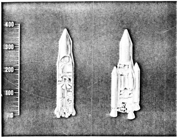
Fig. 6 Astronautics' Class I Configurations
The significant differences in the F-l/M-1 vehicle on the left are the smaller number of engines (16 uprated F-1's in the first stage, 2 M-1's in the second stage), and the use of multicell tanks. The smaller engine number was selected to insure higher reliability and better cost effectiveness. It results, however, in a payload of less than one million pounds (Table 2). The multicell tank design will be discussed later.
The Astronautics vehicle with the solid propellant first stage and the LO2/LH2 second stage is shown on the right in Fig. 6. A parallel staging arrangement is used, with the first stage solid motors mounted at the sides of the second stage. Parallel staging leads to considerably shorter vehicles than tandem staging and permits greater flexibility in payload shape; the height of the launch buildings is also reduced. It has the disadvantage, however, of a more complex staging sequence with its attendant development problems. At staging, the second stage engines are started first; the solid motors are then made to pivot outwards around the thrust pickoff points, located near the nozzles, by kick rockets mounted in the forward fairings. Solid motor thrust is then neutralized and the entire first stage thrust structure is released.
Four solid motors of 325 in. diameter, with gimballed nozzles, are used in the first stage. This motor size is considered to be within the upper range of the technology level being developed under the current large solid motor demonstration program. The lift-off thrust-to-weight ratio is characteristically higher for solid propellant vehicles than for liquid propellant ones, about 1.4 as opposed to about 1.25 for a typical liquid propellant design. Four M-1 engines are used in the second stage. As may be expected on the basis of the specific impulse relationships between the stages, a relatively large LO2/LH2 second stage is required to provide optimum performance in conjunction with a solid propellant first stage. The second stage tank structure, which forms the core of the vehicle, is of multicell design, 67.5 feet in diameter.
The Martin solid propellant vehicle, Fig. 5, is significantly different in its use of the tandem design. It has the advantage of a considerably simpler staging sequence, and the disadvantage of greatly increased height. Five M-1 engines are used in the second stage, permitting the use of smaller, 300 in. diameter solid motors in the first stage. With 5 second stage engines, engine-out capability is required in the second stage. The major characteristics of the four Class I vehicles are listed in Table 2.
|
Table 2 |
||||
|
First Stage Propellants |
LO2/RP-1 |
LO2/RP-1 |
SOLID |
SOLID |
|
Vehicle Designation* |
GD/A-B |
M/B-IC |
M/B-14A |
GD/A-1 |
|
Payload to 121 n.mi. (106 lb.) |
0.81 |
0.98 |
1.06 |
1.14 |
|
Max. Payload Dia. (ft ) |
67.5 |
60 |
60 |
67.5 |
|
First Stage Engines |
16 F-1 (+) |
18 F-1 (+) |
4 x 300" |
4 x 325" |
|
Second Stage Engines |
2 M-1 |
3 M-1 |
5 M-1 |
4 M-1 |
|
Lift-off Thrust (106 lb ) |
28.8 |
32.4 |
47.2 |
56.2 |
|
Lift-off Weight (106 lb ) |
23.0 |
25.2 |
33.7 |
39.7 |
|
Lift-off T/W |
1.25 |
1.29 |
1.40 |
1.42 |
|
Height, less Payload (ft ) |
237 |
326 |
380 |
224 |
|
Max. Base Diameter (ft ) |
85 |
89 |
75 |
128 |
|
* GD/A: General Dynamics/Astronautics. M/B: Martin/Baltimore (+) Uprated F- 1 @ 1.8 million lb thrust |
||||
The Class II or advanced NOVA vehicles are shown in Figs. 7 and 8.
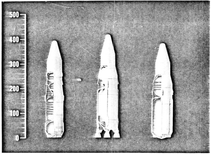
Fig. 7 Martin Class II Configurations
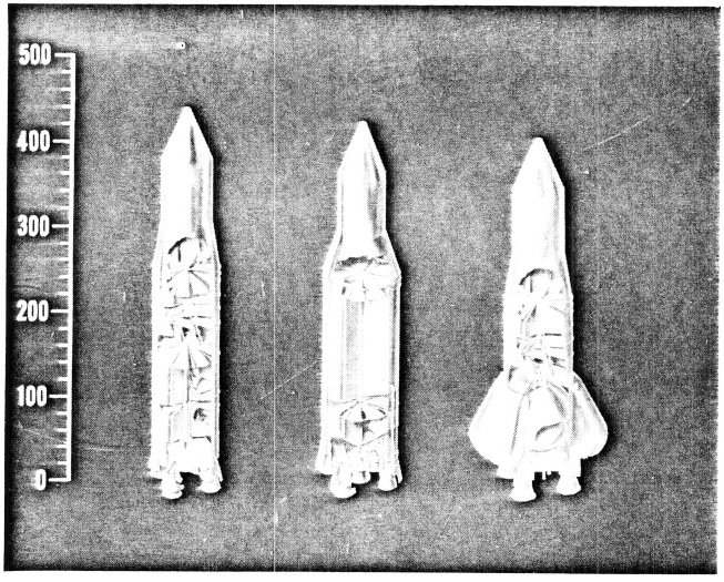
Fig. 8 Astronautics' Class II Configurations
The Martin designs are illustrated in Fig. 7. The first vehicle is a two-stage system using LO2/LH2 propellants in both stages. The use of the high energy oxygen-hydrogen combination in the first stage results in a lighter vehicle and also makes possible the employment of the same basic engine modules in both stages. It has some disadvantages associated with the use of a higher cost, lower density propellant, which requires a physically larger vehicle and more costly launch facilities.
The first stage propulsion system is of particular interest. Eighteen advanced, high chamber-pressure engines are arranged around the lower periphery of the stage in what is termed a zero-length plug cluster. The plug cluster is extremely attractive from the installation viewpoint; it permits a substantial saving in vehicle length and a simplified thrust transfer structure. It also offers the promise of improved engine performance due to its altitude compensating characteristics. As is well known, the optimum expansion ratio for a conventional bell-nozzle rocket varies with ambient pressure, i.e. , with altitude. A rocket with a fixed expansion ratio nozzle therefore operates at less than optimum efficiency at all altitudes other than the one which corresponds to its design point. In the basic plug concept, an annular jet formed by a ring of rocket nozzles is directed inward along a centrally located "isentropic spike" or "plug." If the expansion ratio of the individual nozzles is correct for the ambient pressure, say at sea level, the jet simply follows the plug contour. As the ambient pressure is decreased, the outward boundary of the jet is deflected further and further outwards; the momentum required for this deflection is transferred to the plug by the gas pressure in the jet; the plug now acts as a variable nozzle, adjusting the effective expansion ratio to the prevailing altitude condition. There are indications that it may not be actually necessary to install an isentropic plug at the center of the jet. Even without a plug (i.e. , with a zero-length plug) the pressure in the cone-shaped space within the annular jet may be expected to stabilize at an appropriate value and, by acting on the base area of the vehicle, accomplish the desired momentum transfer. The plug arrangement not only offers considerable performance gains at lower altitudes through its altitude compensating properties , but, by utilizing the whole base area of the vehicle as the effective nozzle exit area, it also offers a means of achieving very high expansion ratios in vacuum without requiring unwieldy nozzle designs.
The plug concept has its share of uncertainties. The extent to which altitude compensation actually takes place is as yet uncertain; in particular, the behavior of a plug at higher vehicle Mach numbers, in supersonic flow with base flow separation, is as yet unknown. With the large number of engine modules required in the cluster, engine out capability must be provided. The loss of an engine will affect the flow pattern of adjacent engines and may have adverse effects on the performance of the entire cluster and on the direction of the composite thrust vector. When an engine has to be shut down, it may also be necessary to shut down the opposite engine in the cluster. Finally, differential throttling or secondary fluid injection, or both, may be required for thrust vector control. The effectiveness of these methods and the performance penalties associated with their use will have to be determined by experiment.
As a result of the high performance associated with the propulsion system, a lift-off weight of only 14.4 million pounds is predicted for the vehicle under discussion, requiring a lift-off thrust of 18 million lb. Each of the 18 engine modules in the cluster is rated at one million pounds thrust. Two of the same engine modules, with a higher expansion ratio bell nozzle, are used in the second stage, thus requiring only one advanced engine development.
The very attractive features of this vehicle emphasize the need for a vigorous research program aimed at developing altitude compensating systems, measuring their performance, and resolving their uncertainties.
A different approach to the design of the two-stage vehicle can be seen in the Astronautics configuration shown on the left in Fig. 8. This vehicle uses LO2/RP-l propellants in the first stage. First stage propulsion consists of 4 large, high pressure bell-nozzle engines. Oxygen-hydrogen propellants and 2 M-1 engines are used in the second stage. The tanks are of multicell construction. The use of RP-1 in the first stage leads to a heavier vehicle, which in turn requires a higher lift-off thrust. On the other hand, higher propellant density (resulting in smaller tanks), lower propellant cost, and significantly cheaper launch facilities [*] lead, on balance, to a vehicle with a better cost effectiveness than that of a similar vehicle using hydrogen in the first stage.
[*- Howard Keyser, ibid.]
The small number of engines offers improved vehicle reliability. The large, high performance bell-nozzle engines represent a direct extension of present state-of-the-art. Their use avoids the uncertainties associated with altitude compensating systems. This vehicle thus lends itself to an early program go-ahead, with good confidence in achieving its predicted characteristics.
Turning now to the 1-1/2 stage concepts, we can start with the GD/A configuration shown in the center of Fig. 8. The propellants are oxygen-hydrogen. The propulsion system consists of 4 booster engines and one centrally located sustainer engine. The sustainer engine is identical to the booster engines except for an increased expansion ratio nozzle. All 5 engines are ignited at lift-off, but the 4 booster engines are shut down and jettisoned at the end of the booster phase while the sustainer engine continues to operate for the remainder of the flight. A single set of propellant tanks is used, leading to a great simplification of the vehicle structure. The tanks shown here and in the previous GD/A vehicles are of multicell design; the outer skin of the tank is scalloped and is restrained by tension webs radiating from a central core. The relatively small radius of curvature of the cell wall results in thinner tank skins, yet the structure provides high strength in bending and compression. The bulkheads are formed by a radial array of conical segments. A substantial weight saving is achieved as a result of the shorter inter-tank and interstage adapters made possible by the nearly flat bulkheads. The central core of the multicell tank can serve as a convenient pathway for propellant feed lines. Multicell construction also promises advantages in manufacturing, due to the lighter skin gages, reduced lengths of multipass welds and smaller numbers of compound curvature pieces. Further definition is required, however, of the stress analysis methods and manufacturing techniques applicable to the multicell design. Large scale experiments in these areas have been started at the Marshall Space Flight Center.
The 1-1/2 stage vehicles tend to be larger than 2-stage vehicles because of the reduced gains due to staging, and they also are considerably more sensitive to variations in engine performance and vehicle mass fraction, i.e. inert weight. Although the 1-1/2 stage vehicles are larger, their greater simplicity makes their cost effectiveness comparable to that of the 2-stage vehicles. A greater development risk must be assessed against them, however, as a consequence of their higher peformance sensitivity.
The Martin design for a 1-1/2 stage vehicle, shown in the center of Fig. 7, is quite similar to the GD/A design, except that altitude compensating expansion-deflection engines are used. These engines are similar to plug clusters, but with the annular jet initially directed radially outwards and then deflected along the inner face of a modified bell contour .
An example of a single stage to orbit vehicle is shown on the right in Fig. 7. This Martin design has 24 engines of 1.25 million pounds thrust each, arranged in a plug configuration. The propellants are oxygenhydrogen. Single stage vehicles are attractive because of their simplicity in design and operation, and the related promise of superior reliability. They tend to be even more sensitive to propulsion system performance and vehicle weight variations than 1-1/2 stage vehicles. The development risk is consequently high. In order to be competitive at all, excellent levels of engine specific impulse and vehicle mass fraction must be assured. The cost effectiveness of single stage vehicles, even when they are designed at the best levels of technological advancement that can be projected for Class II NOVA programs, is not as good as that of the 2-stage or 1-1/2 stage vehicles. The single stage to orbit concepts must therefore await the introduction of more advanced design and propulsion technologies.
As has been stated earlier, one of the most promising avenues for improving the cost effectiveness of large launch vehicles is the development of recoverable and re-usable systems. The first step may be the recovery of the engines, which represent a large fraction of the vehicle cost. The NOVA studies do indicate that recovery of the first-stage engines would pay for itself within a reasonable program span. The next step is the recovery of the complete stage under conditions which make its re-use both practical and economical. A configuration designed to accomplish this is shown on the right in Fig. 8. This GD/A vehicle consists of two stages, a conventional expendable second stage and a fully recoverable first stage.
The first stage is shaped to enhance its atmospheric re-entry, water impact, and flotation characteristics. The shape shown here is hypersonically stable. The large (140 ft ) diameter provides the low weight-to-drag ratio required to minimize heating during re-entry. After second stage separation, the first stage follows a ballistic trajectory and enters the atmosphere at approximately the same velocity as existed at staging (Fig. 3). The re-entry conditions are thus reasonably favorable, and it appears that substantially no added heat protection will be required for the aluminum structure. When the stage has been slowed down to subsonic speeds, large parachutes are deployed from the aft end to reduce the rate of descent. Just prior to water impact solid propellant retro-rockets installed in the forward dome are fired to further reduce the impact velocity. The stage floats in a stable manner with the engines up, far above the water, and it can be towed in this position. As a result, minimum water damage and a reasonably quick and economical turn-around procedure can be envisioned. In many respects this vehicle must be designed more like an airplane than like a booster, with provisions for extended fatigue life, weather protection, maintenance, etc. The turn-around cost, the turn-around time, and the number of times each vehicle is re-used are the critical factors in determining the economics of a recoverable system. Much work needs to be done in the areas of recovery and refurbishment to insure that the full benefits of reusable systems can be realized.
The vehicle shown in Fig. 8 is designed with oxygen-hydrogen propellants in both stages. The first stage oxygen tank is nestled within the cylindrical thrust structure which passes through the large hydrogen tank and also serves to transmit the water impact loads back to the engines. The expendable second stage is similar to previously described designs; it includes multicell oxygen-hydrogen tanks and is powered by 2-M- 1 engines .
Selected characteristics of the Class II NOVA vehicles are listed in Tables 3 and 4. In summary, it appears that the Class II NOVA is more likely to be a 2 stage than a 1-1/2 stage vehicle. It will certainly use advanced rocket engines, hopefully of the altitude compensating type. It will incorporate recovery, preferably of the entire first stage, but certainly of the first-stage engines. It will be an efficient vehicle; depending on the size of the space launch program it supports, it may approach cost effectiveness levels of 50 $/lb. Work under the NOVA studies is now aimed at further examining and resolving some of the questions touched upon previously, such as the relative merits of RP-1 and hydrogen as first stage fuels. At the same time the areas of advanced technology which will show the greatest return in improving launch vehicle design are becoming evident. Foremost among these are altitude compensation, improved recovery techniques, and advanced structures.
|
Table 3 – 2-STAGE NOVA VEHICLES - CLASS II |
|||
|
Vehicle Designation* |
M/B-24G |
GD/A-F |
GD/A-J |
|
Payload to 121 n.mi. (106 lb) |
0.99 |
1.13 |
1.12 |
|
Max. Payload dia. (ft) |
60 |
67.5 |
67.5 |
|
First Stage Type |
Expend. |
Expend. |
Recov. |
|
First Stage Fuel |
LH2 |
RP- 1 |
LH2 |
|
First Stage Engine Type |
Plug |
Bell |
Bell |
|
First Stage Engine No. |
18 |
4 |
4 |
|
Second Stage Engines |
2 @ 1 M lb |
2 M-1 |
2 M-1 |
|
Lift-off Thrust (106 lb) |
18 |
32 |
25 |
|
Lift-off Weight (106 lb) |
14.4 |
26.4 |
20.2 |
|
Height, less Payload (ft|) |
258 |
276 |
233 |
|
Max. Diameter (ft) |
76 |
86 |
139 |
|
* M/B: Martin/Baltimore . GD/A: General Dynamics/Astronautics |
|||
|
Table 4 – 1 AND 1-1/2 STAGE NOVA VEHICLES - CLASS II |
|||
|
Vehicle Designation* |
M/B-34 |
GD/A-H |
M/B-33 |
|
Payload to 121 n.mi. (106 lb) |
1.17 |
1.14 |
1.04 |
|
Max. Payload dia. (ft) |
80 |
85 |
80 |
|
Number of Stages |
1-1/2 |
1-1/2 |
1 |
|
Engine Type |
E.D. (**) |
Bell |
Plug |
|
No. of Engines |
4 + 1 |
4 + 1 |
24 |
|
Lift-off Thrust (106 lb) |
30 |
26 |
30 |
|
Lift-off Weight (106 lb) |
24.0 |
21.0 |
24.2 |
|
Height, less Payload (ft) |
278 |
240 |
249 |
|
Max. Diameter (ft) |
108 |
105 |
86 |
|
* – M/B: Martin-Baltimore. GD/A: General Dynamics/Astronautics (**) Expansion-Deflection |
|||
With the Class I and Class II vehicles now reasonably well defined, NASA has asked the NOVA study contractors to look further into the future, at unconventional NOVA concepts, to see what might be possible if no constraints were imposed on the operational availability dates. The Class III NOVA would almost certainly be a fully recoverable, single-stage or partially staged (e . g. 1-1/2 stage) vehicle, with great mission and payload flexibility. To achieve its objectives, it could draw upon the most advanced concepts in propulsion and structures. I would like to touch only briefly on two possible directions in which the Class III NOVA might develop.
Figure 9 shows the extension of the recoverable first stage design concept of Fig. 8 to the 1-1/2 stage and single-stage configurations.
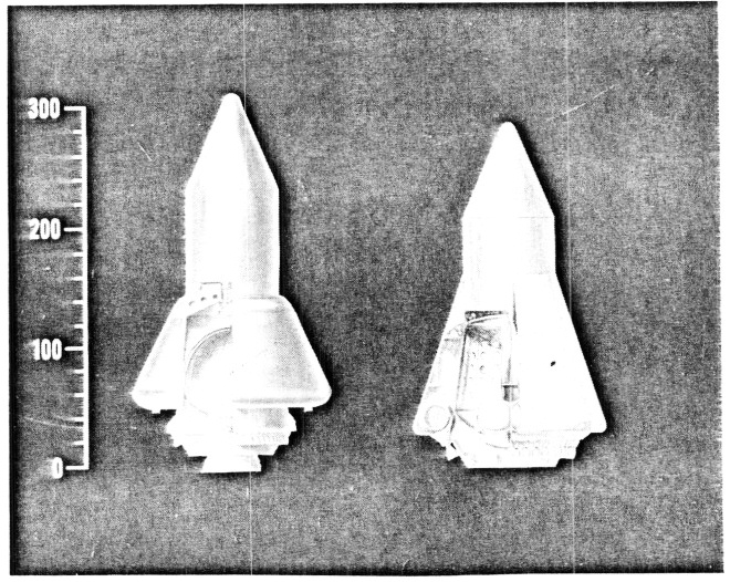
Fig. 9 Astronautics Class III Concepts--Nexus
If the full potential of altitude compensation can actually be realized, then a fully recoverable 1-1/2 stage design, like the one shown on the left in Fig. 9, may become economically competitive. The booster engines would be recovered separately, and the entire tankage would be placed in orbit. This has a big operational advantage, since the stage may then be made to re-enter and land very close to the launch site after one complete orbit. However, the development problem is now much more severe, since re-entry has to take place at orbital velocities. The single-stage configuration which is shown on the right in Fig. 9, also known as the Nexus concept, is even more attractive from an operational viewpoint, since only one object has to be recovered. To be competitive, a single-stage vehicle like this requires substantial advancements in mass fraction and propulsion efficiency.
Mass fraction could be improved significantly by the use of more advanced structural materials, such as titanium. The application of titanium to very large vehicles is dependent, however, on a substantial reduction in the high fabrication costs presently associated with titanium structures. Much manufacturing development work needs to be accomplished here before the weight gains associated with titanium can be translated into economical vehicle designs.
A possible method for improving propulsion efficiency is air augmentation. A recent embodiment of this approach is shown in Fig. 10, which illustrates the Renova concept developed by Martin.
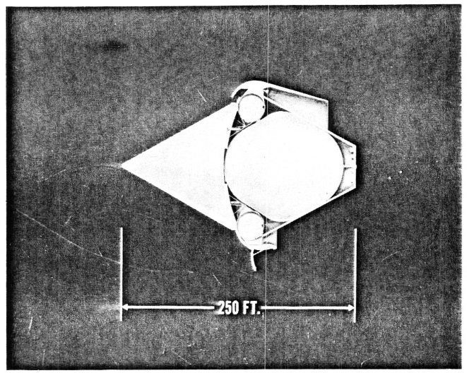
Fig. 10 Martin Class III Concept--Renova
The rocket engines are arranged in a ring around the major diameter of this single-stage vehicle. The hydrogen tanks form what is, in effect, a large plug, with a toroidal oxygen tank mounted forward. The rockets are enclosed in an air duct equipped with adjustable inlets. A jettisonable shroud extends the mixing area downstream of the rockets. The conical payload fairing serves as an inlet spike during the ascent through the atmosphere. The air enters through the inlet, mixes with the rocket exhaust, is heated and expands past the plug-shaped after-body, thus contributing additional thrust. The mixing shroud is jettisoned and the inlets are closed after leaving the atmosphere. The engines now operate in the pure rocket mode. When the payload is separated and the flaps are extended (lower half of Fig. 10), the vehicle assumes a favorable re-entry shape. The location of the engines insures a forward center-of-gravity position and good stability. Re-entry and recovery take place in the same manner as described earlier.
It is hard to predict at this time what the actual characteristics of these Class III systems will turn out to be after more thorough analysis, and what other concepts or variations may develop in this very advanced area.
Looking back over the several possible NOVA embodiments, we can say that depending on the timing of the space missions which NOVA will be called on to support, one of three possible alternatives might be followed. These are shown schematically in Fig. 11.
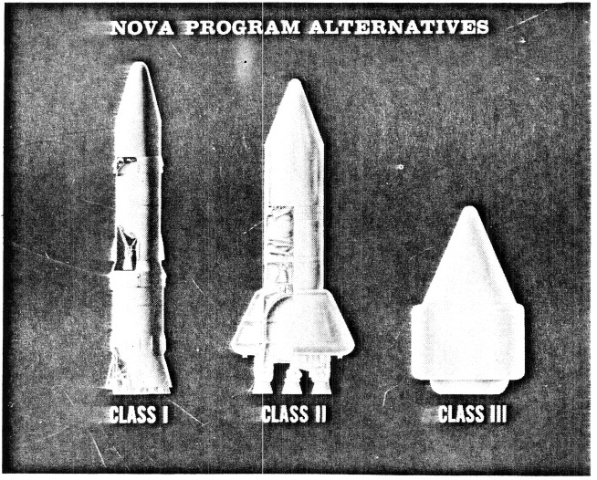
If an urgent requirement materializes in the immediate future, the development of a Class I NOVA using F-1 and M-1 engines can be started almost immediately. If a more orderly requirement is established within the next several years, an advanced, recoverable Class II NOVA can be developed, using improved rocket engines. If the requirement is further delayed, an even more advanced Class III NOVA may eventually be developed. Any one of these vehicles will fully meet the physical requirements of a manned Mars expedition as we envision it today. The major difference will be in the economy with which they will perform the task.
1. K. A. Ehricke, et al., A Study of Early Manned Interplanetary Missions, General Dynamics/Astronautics Report AOK63-0001, Jan., 1963 (43.3 MB PDF)